
Table of Contents
Milling Machine
Milling Machine is a versatile machine tool. Through which many types of operations are done with the help of a multi-point cutter. These cutters are run by holding the milling machine spindle with an arbor, adapter or collet chuck. And under the rotating cutter, the bottom of the job is made by forming the bottom of the job. These cutters are manufactured in different sizes and shapes. Through which every kind of work becomes easy.
The first milling machine was invented in France in 1770. Then this machine was developed by Jock D. Baukanson in 1782. After this, the design of the Plane Milling Machine was designed by Alibit in 1818. And in order to use this machine properly, different types of cutters, cutting and feed speeds were fully introduced and proved that this machine is also like Lathe Machines.
Also this machine is useful for mass production works. And for metal cutting, it is more useful than machines like Shaper Machine and Planer Machine. With this introduction, in 1861, an engineer named Joseph R Brown first designed the improved design of the milling machine.
Working Principle
The job is clamped firmly to the machine table to perform any work on the milling machine. And the cutter is applied to the arbor or spindle. The cutter rotates at a fixed speed and the job is passed slowly under the cutter. Therefore, when the job comes in contact with the moving cutter, the cutter’s teeth (Teeth) cut the metal in the form of chips from it. The jobs on the table can be fed in longitudinal, cross-wise and vertical in all three directions.
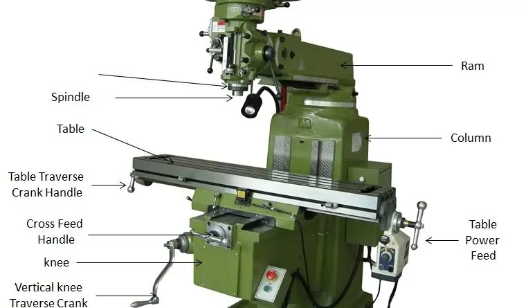
Milling machine parts name
Main parts of the milling machine
1. Column and base
The column is the base of the milling machine. It is mounted vertically on the base. Supports the knee, table, arm, etc. It works as accommodation for all other booster members. It is a hollow member consisting of a drive gear and sometimes a motor for the shaft and table.
2. Knee
The knee is the moving part of the router. The chair and table support the casting. The gear device is included within the knee. The knee is attached to the abutment using the Dowell methods.
3. Saddle and rotary table
The saddle is at knee height and supports the table. The saddle slides on the horizontal dovetail at the knee and the dovetail is parallel to the axis of the axle. A turntable is attached to the saddle that rotates horizontally in both directions.
4. Power Feed mechanism
The power feed mechanism is in the knee. It is used to control longitudinal, transverse, and vertical feeds. For the desired rate of feed on the machine, the feed selection lever is positioned to point at the feed selection plates.
5. Table
The table is a rectangular casting that is present in the upper part of the saddle. The table is used to hold a task or for workpiece clamping devices. There are several T-slots to hold the workpiece and hold the equipment. It can be done by hand or with a motor. To move the table by hand, turn and turn the crank on the longitudinal arm.
6. Husillo
Se coloca entre la mesa y la rodilla y actúa como pieza intermedia entre ellas. Esta columna puede moverse transversalmente sobre la cara. Se desliza sobre guías que se ubican en la rodilla que son perpendiculares a la cara de la columna. Su función principal es mover la pieza de trabajo en dirección horizontal. También está hecho de hierro fundido.
7. Over arm / Overhang arm
It is a cantilever on the surface of the column and the other end supports the arbor. It can be a single pour and slide that sits at the top of the column as a block. Over arm is located on top of the column on a horizontal milling machine. It is made of cast iron.
8. Arbor support
The axle bracket is cast with a bearing that supports the outer end of the axle. It also helps align the outer end of the tree with the axle. The tree support prevents the outer end of the tree from popping out in a cutting operation.
9. Ram
Rams serve as the upper arm on a vertical mill. One end of the ram is placed on top of the abutment and the router head is attached to the other. One end of the arm is attached to the abutment and the other end is attached to the milling head.
Classification
The milling machine can be classified as follows
1. By Position of Milling Spindle –
(i) Horizontal Spindle
(ii) Vertical Spindle
(iii) Horizontal and Vertical spindle.
2. By number of milling spindles –
One, two or more milling spindles
According to the work, the milling machine is classified in many ways. Mainly this machine is selected according to the nature of the work and attention is also given to the size of the work. Generally, it is prepared in many forms and sizes depending on the design.
3. Based on design
Types of Milling Machine
Column and knee type milling machine
This type of milling machine is often the most used in machine shop. The table of this machine is placed on the knee. It is fitted on the steep passages above the Column. By speeding up this part, the table can be raised anywhere at different heights up and down.
The instruments giving different speeds to the table are also fitted in this part. The pillar and knee type milling machines are classified as follows
(A) Hand Milling Machine
This milling machine is of the simplest type and this machine is used to perform small and simple operations. All three feed speeds of this machine are given by hand. This machine is very useful for cutting slots, especially the small slots.
(B) Plain Milling Machine
This machine is stronger and larger in size and design than a hand milling machine. The arbor of this machine is also Horizontal. This machine can be given speed both by hand and automatic. The table of this machine is situated at right angles so that all plain milling operations can be done easily by the machine.
(C) Universal Milling Machine
This machine is also similar to a plane milling machine. But the difference is that the table of this machine can be set anywhere between 0 ° to 45 ° by turning left, right.
Due to this angular momentum of the table, helix can be easily cut, such as helical gear, slot and groove. The working capacity of this machine has been increased by a number of attachments.
All types of gears, cutters, cams, drills, reamers, die and punch, jig and fixtures with the help of attachments, jig and fixtures Fixture) can be prepared. Often this machine is used in the tool room.
(D) Omniversal Milling Machine
The table of this machine can also be tied to the vertical floor by rotating it at any angle from the bottom to the top and bottom to the top of the table of the universal milling machine, thus the table of this machine can be given relatively more speed. . That is, five types of feed movements can be given. like
1. Longitudinal
2. Inward and outward i.e. crosswise
3. Up and Down
4. Horizontal Angular
5. Vertical Angular.
Due to the arrangement of this additional motion of the table, the machining can be done easily by using helical or bevel gears, cams special dies and profile of tools. This machine can be used natively in experimental shops, labs and tool rooms.
(E) Vertical Milling Machine
The spindle of this machine is vertically vertical and the spindle head can be clamped on either side by rotating it at any angle from 0 ° to 90 °.
The spindle of this machine can also be lowered up and down like a drilling machine.Drills, End Mill, Shell End Mills, Facing Cutters and some similar Shank cutters can also be clamped on this machine.
By which T-slot, Dove Tail, Segment, Grooving, Boring, Drilling, Recessing, Cam Milling, Profiling (Profiling), Die Sinking, etc. milling operations can be done
(F) Ram Type Milling Machine
In this machine, the cutter head is mounted on the face of a ram. By which the cutter head can be set on both sides by rotating at any angle in the Vertical and Horizontal Plain and the ram which has a spindle which is inward and outward cross feedment.
Can be given.In this type of machine, the work-table is fitted on the saddle with the help of a nut bolt over the standing side passages above the column ie the length of the work-table on the saddle. There is also a provision of upward and downward motion.
This machine is equipped with a lot of equipment (with the help of which the cutting operations of this machine can be increased). It is also a very useful machine for the experimental shop.
Manufacturing or Fixed Bed Type Milling Machine
As these names suggest, the tables of these machines are fixed above the bed and can be given only by attachment ie their tables are neither moving up or down in cross direction. Can.
Due to the bad fix of these machines, heavy cuts can be made on them. These machines have a vertical column. On which routes are made to run spindle head.
This spindle consists of Arbor. To cut the work, the spindle head is moved up and down along the routes on the column and the work is clamped to the table in such a way that the machining of the work is completed only once from the bottom of the cutter.
These machines, being relatively heavy and robust, are used for multi-product operations. These machines are classified as follows.
(A) Simplex Milling Machine
This machine has only one spindle head in which the cutter is held by applying arbor. These spindle heads can be tightened up or down anywhere on the column according to the height of the work.
(B) Duplex Milling Machine
This machine is fitted with two different cuttter heads. These cutters are adjusted by sliding up and down on two columns fitted on the sides of the head bed. These cutter heads can also be used simultaneously or separately. Thus on this machine two floors can be machined simultaneously.
(C) Triplex Milling Machine
In this machine, two cutter heads are fitted like a duplex milling machine. The third cutter is mounted on a cross-rail fitted above the head column. This cutter can be run at different speeds for head harvesting. These cutter heads can be quickly moved from one place to another for harvesting operations.
Planer type Milling Machine
It is also called Plano milling machine. Planer typemilling machine is similar in appearance to a planning machine. It is a heavy machine. The cross-rail of this machine is replaced by a cutter head in place of the tool head.According to the work height, the height of the cross-rail can be adjusted anywhere above or below the housing. This cutter head can be more than one.
Some machines have one or two side cutter heads on the side of the housing like a planer. By which all the three floors of work are created at the same time. These cutter heads can also be used independently. As a result, there is a lot of savings in production time.
The main difference in Miller is in his table motion. Table speed in plane milling machine is much slower than in planer machine. This machine is designed for very heavy work and machining of large size planks. Usually, 20 to 70 horse power motors are used to run such machines, due to which these machines are used for large production.
Special Purpose Milling Machine
These machines are designed to serve a particular purpose. Use of these has given a boost to production and quality has also improved. By using these machines, there is very less chance of the work getting spoiled. All the parts manufactured by them are made in the same size and shape, which maintains interchangability in the parts. These machines have been classified according to work.
(A) Rotary table milling machine
The table of this machine is round. This table passes the job under the rotating cutter. More than one cutter can also be used on this machine. The loading and unloading of the job can be done to perform continuous cutting process on this machine. This machine is often used specially for the facing process.
(B) Profiling Machine
This machine is similar to a bad type vertical milling machine. In which the spindle can be moved up and down and back and forth in the lying floor. This machine is used to prepare a full-size template over the job. This machine has one to four spindle heads in which end mill cutters are caught.. In this machine, the movement of the cutter head is controlled by a tracer or guide pin. Which moves touching the outer surface of the template and thus the tracer follows the same path as the shape of the template. This template is fitted on the table on one side of the job. This machine is also called Die Sinking Machine. This machine is used to prepare special die or tool etc.
(C) Planetary Milling Machine
The machine derives its name from the cutter following its planetary path. These machines are available in Vertical Spindle or Horizontal Spindle. On this machine both external and internal round planks can be constructed separately or together.In this, the work is constant and the cutting or feed speeds are given to both the cutters ie in this the cutter cuts around the job moving like the planetary path and moves along. Generally this machine is used for cutting internal and external bangles of different pitch.
(D) Panto Graph Milling Machine
This machine is available in two or three Dimensional models. Two dimensional pantographs are used to mimic letters or other designs. Three dimensional pantographs are used to mimic each type of shape or contour, and the size can be reduced or increased in proportion.A pantograph is a mechanism that consists of four rods or links and lives in the shape of a parallelogram. With the help of this mechanism, you can make the size of the shape on the job by decreasing or increasing the proportion according to the shape of the template or model. This machine is often used exclusively for digging.
(E) Drum type milling machine
This machine is similar to a rotary table milling machine. The table of this machine, called a drum, rotates under four spindles simultaneously in a rounding. On which the machine poons are removed when a round of drums is completed. And new parts are clamped in their place.
(F) Tracer Control Milling Machine
This machine is used for the manufacture of special types of soils in die and molds. Whether those floors are regular or the feed to irregular jobs is controlled by a special type of method called Servo Mechanism. It revolves around a job made according to the profile of the template or contour made in Stylus.This move of the stylus drives an Oil Relay System and thus the table starts to move through a fluid driven system, which automatically cuts the work segment tied to the table.
(G) Gear Hobbing Machine
As its name suggests, this machine is used only to cut down on the production rate. In this, all types of gargles such as Spur can be cut accurately. Hob cutter is used to cut teeth in it.
In this, along with the hob cutter, the job keeps on kissing and the indexing is done by the machine itself for the cutting of teeth. In this way, many garrisons can be cut at one time. Under this class, there is also another machine for cutting gears, which is called gear. Its function is also similar to hobbing.
(H) Thread Milling Machine
This machine is used by cutting milling cutters to cut acmi or worm chicks etc. as the bangles are cut with more precision and cleanliness by this operation. Commonly, cutters are used to cut bangles of course pitch and multi-tooth cutters are used to cut bangles on less elongated parts.
(I) N.C. and C.N.C. Milling Machines – Nowadays in modern shops, N. C. and C.N.C. milling machines are used. These are very modern machines. The program is designed and fed to the control unit according to the job drawing.
Maintenance of Milling Machine
Maintenance of a milling machine is crucial to ensure its optimal performance, longevity, and safety.
Some general guidelines for maintaining a milling machine:
Regular Cleaning:
Clean the machine regularly to remove chips, dirt, and debris. Use a brush, vacuum, or compressed air to clean the milling machine thoroughly.
Wipe down surfaces with a cloth dampened with a mild detergent to remove grease and oil.
Lubrication:
Follow the manufacturer’s guidelines for lubricating various parts of the machine. Lubricate the slides, gears, bearings, and other moving parts to prevent wear and friction.
Check and refill lubricant levels according to the recommended schedule.
Check and Tension Belts:
Regularly inspect the belts for signs of wear, cracks, or damage. Adjust or replace them as necessary.
Ensure proper tension in the belts for optimal power transmission.
Inspect and Tighten Fasteners:
Regularly inspect all bolts, nuts, and screws for tightness. Vibration and use can cause them to loosen over time.
Use a torque wrench to ensure that fasteners are tightened to the manufacturer’s specifications.
Check and Calibrate the Machine:
Periodically check and calibrate the machine to ensure accuracy in cutting. This includes checking the alignment of the spindle, table, and other critical components.
Use precision measuring tools to verify the accuracy of the machine’s movements.
Inspect Coolant System:
If your milling machine has a coolant system, inspect it regularly. Ensure that coolant levels are adequate and that the system is functioning properly.
Clean or replace the coolant filter as needed.
Inspect Electrical Components:
Regularly check electrical components, such as wiring, switches, and controls, for signs of wear, damage, or malfunction.
If any issues are identified, address them promptly to prevent safety hazards.
Advantages and Disadvantages of Milling Machine
Milling machines are versatile tools used in machining processes to shape, cut, and fabricate materials. They come with various types and configurations, each with its own advantages and disadvantages. Here are some general advantages and disadvantages of milling machines:
Advantages:
Versatility:
Milling machines can perform a wide range of operations, including face milling, end milling, slot milling, drilling, and more. This versatility makes them suitable for various applications in manufacturing.
Precision:
Modern milling machines are capable of high precision and accuracy. Computer Numerical Control (CNC) milling machines, in particular, offer exceptional precision in machining complex parts.
Efficiency:
Milling machines can remove material quickly, making them efficient for mass production. This efficiency is especially beneficial in industries where large quantities of identical or similar parts are required.
Automation:
CNC milling machines can be automated, allowing for the production of complex parts with minimal human intervention. This results in increased productivity and consistency.
Material Compatibility:
Milling machines can work with a wide range of materials, including metals, plastics, and composites, making them suitable for diverse applications across industries.
Customization:
Milling allows for the customization of parts with intricate shapes and features. This is particularly valuable in industries such as aerospace and medical, where complex components are common.
Tooling Options:
Various types of cutting tools can be used in milling machines, allowing for a broad range of machining possibilities. Different tool geometries and coatings can be selected based on the specific requirements of the job.
Disadvantages:
Cost:
Milling machines, especially CNC versions, can be expensive to purchase and maintain. The initial investment includes the machine itself, tooling, and the cost of training operators.
Space Requirements:
Milling machines, particularly larger ones, require significant floor space. This can be a limitation for small workshops or manufacturing facilities with space constraints.
Complexity:
Operating and programming CNC milling machines can be complex. Skilled operators and programmers are needed to optimize the machine’s capabilities fully.
Maintenance:
Regular maintenance is required to ensure the milling machine operates efficiently and produces accurate results. Maintenance can involve the replacement of worn-out tools, checking and calibrating the machine, and addressing any mechanical issues.
Noise and Dust:
Milling operations can generate noise and dust, which may require additional safety measures and environmental controls. Personal protective equipment (PPE) and dust extraction systems may be necessary.
Initial Learning Curve:
Learning to operate a milling machine, especially a CNC version, requires training and experience. The initial learning curve can be steep for operators who are new to the technology.
Limited Accessibility:
Milling machines may have limitations in accessing certain areas of a workpiece, especially if it has complex geometry. This can affect their suitability for certain types of machining tasks.
It’s important to note that the specific advantages and disadvantages can vary depending on the type of milling machine, its size, and the nature of the machining tasks it is used for.
Application of Milling Machine
Milling machines find widespread applications across various industries due to their versatility and ability to perform a variety of machining operations.
Some common applications of milling machines include:
Metalworking:
Precision Component Manufacturing: Milling machines are extensively used for producing precision components in industries such as aerospace, automotive, and tool and die making.
Casting and Forging Preparation: Milling is often used to prepare surfaces for casting or forging processes by removing excess material, achieving the required shape, or creating smooth finishes.
Mold Making:
Milling machines play a crucial role in the production of molds for plastic injection molding, die casting, and other manufacturing processes. They can accurately shape molds with intricate details.
Automotive Industry:
Engine Block Milling: Milling machines are used to machine engine blocks, cylinder heads, and other automotive components to precise specifications.
Prototyping and Production: In automotive design and production, milling machines are employed for prototyping as well as mass production of components.
Aerospace:
Precision Machining: The aerospace industry relies on milling machines for precision machining of components such as aircraft parts, turbine blades, and structural elements.
Aluminum and Titanium Milling: Milling machines are used for working with lightweight yet strong materials like aluminum and titanium commonly found in aerospace applications.
Electronics:
Circuit Board Production: Milling machines equipped with fine cutting tools are used in the production of printed circuit boards (PCBs) for electronics.
Component Machining: Milling is employed for machining small electronic components with precision.
Medical Industry:
Implant Manufacturing: Milling machines are used to manufacture medical implants, prosthetics, and other precision components used in the medical field.
Dental Applications: In the dental industry, milling machines are used to fabricate dental crowns, bridges, and other prosthetic devices.
Woodworking:
Furniture Manufacturing: Milling machines are used in the woodworking industry for shaping and finishing wooden components used in furniture manufacturing.
Cabinet Making: Milling machines help in creating intricate designs and joints in cabinet making.
Plastic Industry:
Injection Molding: Milling machines are used to create molds for plastic injection molding processes, ensuring precision and high-quality molds.
Custom Plastic Parts: Milling is employed to produce custom plastic parts with specific shapes and features.
Prototyping and Rapid Manufacturing:
Product Development: Milling machines are crucial in the rapid prototyping and manufacturing of new products, allowing for quick iterations and design improvements.
Education and Research:
Training and Research: Milling machines are widely used in educational institutions and research facilities for training purposes and conducting experiments related to materials and machining processes.
FAQ’s
What is a milling machine?
A milling machine removes material from a workpiece by rotating a cutting tool (cutter) and moving it toward the workpiece. Milling machines, whether vertical or horizontal, are generally used for machining flat and irregularly shaped surfaces and can be used for boring, boring and cutting gears, threads and slots.
What is the principle of milling?
The cutting action is achieved by feeding the workpiece against a rotating cutter. The workpiece is firmly fixed to the table while rotating a multi-tooth cutter placed on the spindle. The cutter rotates at a fast pace while the material is fed.
You may also like