
How to make hydraulic schematic symbol – Hydraulic symbols
Hydraulic schematic symbols are used in hydraulic diagrams and drawings to represent various components and functions in a hydraulic system. These symbols help engineers, technicians, and other professionals understand the layout and operation of hydraulic systems.

Fixed Valve
This Hydraulic symbol represents a fixed check valve, which allows fluid to flow in one direction only and prevents reverse flow. Fixed check valves are often used to maintain pressure in a hydraulic system or to ensure that fluid flows in the desired direction.

Variable Valves
In hydraulic schematics, variable valves can be represented using specific symbols to indicate their function. Variable valves are often used to control the flow rate or pressure of hydraulic fluid in a system.

Pressure Compensated Valve
A pressure-compensated valve is a type of hydraulic valve used in hydraulic systems to control the flow of fluid (usually oil) in response to changes in pressure. It is designed to maintain a consistent flow rate regardless of variations in system pressure, which can be especially important in hydraulic systems to ensure consistent performance.

Flow Control With A Check Valve
Flow control with a check valve involves using a check valve in a fluid system to regulate or control the direction of flow and prevent backflow. A check valve is a one-way valve that allows fluid to flow in one direction while blocking it in the opposite direction.

Directional Control Valves

2/2 D.C. Valve
A 2/2 DC valve, often referred to as a 2-way, 2-position DC valve, is a type of solenoid valve used in fluid control systems. This valve has two ports and two positions, hence the name “2/2.” It is commonly used to control the flow of fluids, such as liquids or gases, in various applications.

3/2 D.C. Valve
A 3/2 DC (Direct Current) valve is a type of solenoid valve commonly used in pneumatic and hydraulic systems for controlling the flow of fluids or gases. The “3/2” designation refers to the number of ports and the number of positions the valve can assume:
3 Ports: A 3/2 valve has three ports:
Inlet Port: This is where the fluid or gas enters the valve.
Outlet Port (A or B): There are two outlet ports labeled as A and B. Depending on the valve’s position, one of these ports is connected to the inlet port, allowing the fluid or gas to flow through.
Exhaust Port: This is where the fluid or gas exits the valve when it’s not directed to either of the outlet ports.
2 Positions: A 3/2 valve has two possible positions or states:
Normal State (Rest or De-energized): In this position, one of the outlet ports (A or B) is connected to the exhaust port, and the other is closed off from the inlet port. This is the default state of the valve when it’s not energized.
Actuated State (Energized): When an electrical current is applied to the solenoid coil of the valve, it switches to the actuated state. In this state, the connection switches, and the port that was previously connected to the exhaust is now connected to the inlet, allowing fluid or gas to flow through.
3/2 DC valves are typically used for simple on/off control applications, such as controlling the movement of pneumatic cylinders or actuating certain types of machinery. The “DC” in the name indicates that these valves are designed to operate with direct current electrical power sources.

4/2 D.C. Valve
A 4/2 DC valve refers to a type of directional control valve used in hydraulic and pneumatic systems. Let me break down what the numbers and letters in “4/2 DC valve” represent:
Number 4: This number typically represents the number of ports on the valve. In the case of a 4/2 valve, there are four ports. These ports are used for connecting the valve to other components in the hydraulic or pneumatic system.
Number 2: This number represents the number of positions the valve can be in. In a 4/2 valve, there are two possible positions or states that the valve can take. These positions determine the flow of fluid or air through the valve and to the connected components.
“DC”: This stands for “Direct Control,” indicating that the valve is operated by a direct current (DC) solenoid. DC solenoids are commonly used to control the position of the valve spool, which in turn controls the flow of fluid or air through the valve.
So, a 4/2 DC valve has four ports, two possible positions, and is controlled by a DC solenoid. These valves are commonly used in various applications where it’s necessary to control the direction of fluid or air flow in a system, such as in industrial automation, mobile equipment, and other machinery. The specific function and operation of the valve can vary depending on the design and application it is used for

4/3 D.C. Valve
A “4/3 DC valve” typically refers to a type of directional control valve used in hydraulic systems. Let’s break down what this term means:
4/3: This notation represents the number of ports and positions of the valve. In a 4/3 valve:
4 stands for the number of ports. A 4-port valve typically includes two inlet ports (P for pressure and T for tank/return) and two outlet ports (A for the A-side and B for the B-side of an actuator).
3 represents the number of positions the valve can be in. In a 4/3 valve, these positions are often labeled as “A,” “B,” and “P” (pressure). “A” connects the A-side of the actuator to the pressure port, “B” connects the B-side of the actuator to the tank/return port, and “P” blocks all ports.
DC: This stands for “Direct Current.” It indicates the type of solenoid or coil used to control the valve. DC valves are commonly used in applications where precise control is required.
A “4/3 DC valve” is a hydraulic directional control valve with four ports and three positions, and it is controlled using a direct current solenoid or coil. These valves are often used in hydraulic systems to control the direction of fluid flow and, consequently, the movement of hydraulic actuators like cylinders or motors. They are crucial components in various industrial and mobile hydraulic applications.

5/2 D.C. Valve
A 5/2 DC (Direct Current) valve is a type of pneumatic or hydraulic valve used in automation and control systems. The “5/2” designation refers to the valve’s configuration, indicating the number of ports and positions it has. Here’s what each part of the designation means:
Number of Ports (First Number – 5): The “5” in 5/2 indicates that the valve has five ports. Ports are openings through which fluid (usually air or hydraulic fluid) can flow into or out of the valve.
Number of Positions (Second Number – 2): The “2” in 5/2 signifies that the valve has two distinct positions it can be in. These positions determine the flow paths of the fluid through the valve and can be used for various control functions.
Typically, a 5/2 DC valve is used to control the direction of airflow or hydraulic fluid in pneumatic or hydraulic systems. It’s commonly used in industrial automation and machinery to actuate cylinders, control the movement of components, or perform other tasks where precise control of fluid flow is required.
The “DC” part of the designation indicates that the valve is designed to be operated using direct current electrical power, typically in the form of a voltage supply. This means that it can be controlled by applying a DC voltage to the valve’s solenoid, causing it to change its position and thereby control the flow of fluid.

Non return valve
A non-return valve, also known as a check valve or one-way valve, is a mechanical device that allows fluid (liquid or gas) to flow in one direction only. It is designed to prevent backflow or reverse flow of the fluid in a piping system. Non-return valves are commonly used in various industries and applications where it is essential to maintain the flow of a fluid in a single direction and prevent it from flowing back in the opposite direction.
Key features and functions of non-return valves include
One-way Flow: Non-return valves allow fluid to flow freely in one direction while blocking or resisting flow in the opposite direction. This ensures that the fluid moves in the desired path.
Types: There are several types of non-return valves, including swing check valves, lift check valves, ball check valves, and spring-loaded check valves. Each type has its own design and mechanism for controlling flow.
Applications: Non-return valves are used in a wide range of applications, such as water supply systems, wastewater treatment plants, oil and gas pipelines, chemical processing plants, and more. They are also commonly used in household plumbing systems to prevent backflow of water.
Preventing Contamination: In many applications, non-return valves are crucial for preventing contamination of fluids. For example, in a water supply system, a non-return valve prevents contaminated water from flowing back into the clean water supply.
Safety: In certain industries, non-return valves are used for safety purposes. For instance, in the case of a gas pipeline, a non-return valve prevents gas from flowing back into the supply line, reducing the risk of explosions.
Check Mechanisms: Different types of non-return valves use various check mechanisms to control flow. For example, a swing check valve has a hinged disc that swings open to allow flow in one direction and closes to prevent flow in the other direction.
Pressure Drop: Non-return valves introduce some resistance to flow, which can result in a slight pressure drop. The magnitude of this pressure drop depends on the design and size of the valve.
Maintenance: Like any mechanical device, non-return valves require periodic inspection and maintenance to ensure they function correctly. This may involve cleaning, lubrication, or replacement of worn parts.

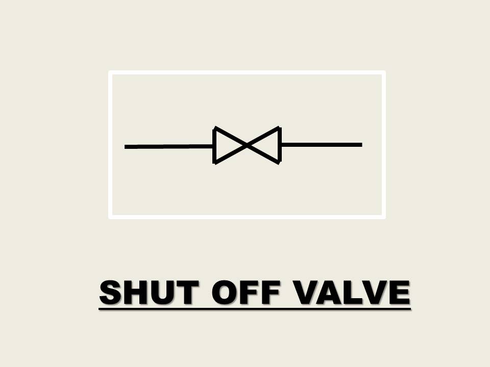
Shut-off Valve
A shut-off valve is a mechanical device used to control the flow of a fluid, typically a liquid or gas, through a pipeline or plumbing system. Its primary purpose is to start or stop the flow of the fluid completely or to regulate the flow by partially opening or closing the valve.
Filter
A hydraulic filter is a crucial component in hydraulic systems used in various industrial and mobile applications. Its primary function is to remove contaminants and particles from hydraulic fluid to ensure the smooth operation and longevity of hydraulic equipment and machinery.

Pump

Unidirectional fixed Delivery Valve
A unidirectional fixed valve is a type of valve used in various fluid control applications to allow the flow of fluid in one direction while preventing it from flowing in the opposite direction. These valves are designed to ensure that fluid can only move through the valve in a specific direction, which is typically referred to as the “flow direction.”

Unidirectional Variable Delivery Valve

How to make hydraulic schematic symbol – Hydraulic symbols
Bi-directional fixed Delivery Valve

Hydraulic schematic symbol – Hydraulic symbols
Bi-directional Variable Delivery Valve

How to make hydraulic schematic symbol – Hydraulic symbols
You may also like