
Table of Contents
Relay
Relay is electrically operated switches that open and close the circuits by receiving electrical signals from outside sources.
The “relays” embedded in electrical products work in a similar way; they receive an electrical signal and send the signal to other equipment by turning the switch on and off.

Types of Electrical Relay
Relay technology can be divided into two main categories: Movable contacts (mechanical relay) and no movable contacts (MOS FET relay, solid state relay).
Movable contacts
( Mechanical Relay )
A magnetic force acts on this type of relay to mechanically open and close its contacts, switching signals, currents, and voltages ON or OFF.
No movable contacts
( MOS FET relay, Solid State Relay )
Unlike mechanical relays, this type of relay has no moving contacts but instead employs semiconductor and electrical switching elements such as triac and MOS FET. By the operation of these electronic circuits, signals, currents and voltages are switched ON or OFF electronically.
Electrical relay Structure and Operating Principles
- Mechanical Relay
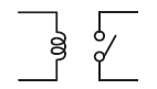
Relay consists of a coil, which receives an electric signal and converts it to a mechanical action and contacts that open and close the electric circuit. - MOS FET Relay
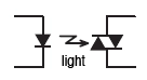
MOS FET relay is a semiconductor relay that uses power MOS FETs in output elements.
Electrical relay Characteristics and Mechanism
Characteristics of Electrical Relay
Mechanical Relay
One of the major characteristics of a mechanical relay is the physical spacing between the coil and the contact component in order to achieve appropriate level of insulation (insulation distance) on both input and output.
MOS FET Relay
One of the major characteristics of a MOS FET relay is that it utilizes semiconductor so the contacts do not mechanically open/close. As a result, benefits include reduction of footprint, quiet operation, longer operating life, and eliminating the need for additional maintenance.
Relay Parts Name
1 ) Relay contacts
An electromechanical relay has these two fixed contacts; “NO” normally open and “NC” normally closed. They share a common mobile contact called “COM” or common. Under normal conditions, a relay can be open or closed.
When de-energized, the contacts are normally closed. When energized, they move to an open position and make contact.
You can think of these contacts as a metal conductor made of elastic material such as beryllium or phosphor bronze alloy.
They have a special welded contact strap. These contact belts are made of high conductivity material with resistance to damage due to electrical sparks.
Alloys of silver, copper, tungsten, nickel, platinum, and gold can make up the conductive belt of an electromechanical relay.
2 ) Electromagnet
The magnetic field is produced when current passes through a conductor.
A coil wound with soft iron core creates a perpendicular magnetic field when current passes through it. This magnetic field when flowing through this soft iron core makes it an electromagnet.
The electromagnet retains its magnetic property as long as the current is on, allowing it to repeatedly turn on and off, playing an essential role in the relay’s functioning principle.
Conventionally, relays usually have latency in the magnetic field. The magnets maintain their magnetic properties after the current is removed.
This is due to the magnetic lag created due to hysteresis, a hysteresis is a magnetic phenomenon where the magnetic induction in a product lags behind its own magnetic field/strength.
3 ) Movable armature
An armature in the relay is that moving conductor that makes or breaks contact based on the magnetic flux of the iron core.
When energized, these armatures pull against spring tension to make or break contact based on the normally closed/normally open relay type.
4) Yoke
A yoke in an electromechanical relay is that piece of metal attached to the soft iron core that does the job of holding and attracting the armature.
Small metal pieces are attached at the top of the central element. The lead wire connects the yoke to the hinged armature in many designs.
It ensures the connectivity/continuity of the current between the contacts and the mobile armature. The other main function of the yoke is to provide a low reluctance path for magnetic flux to flow.
Ideally when we look at an electromagnetic relay; we find an energizing coil called primary circuit. A primary circuit has two key parts, one is movable and spring loaded.
This part is called the truss while the other part that remains fixed is called the yoke. When power is supplied to the energizing circuit; yoke pull the movable armor towards itself closing the air gap in between. In the production of modern yokes, layers of composite material are placed between ferromagnetic material.
5) Spring
Not all relays have a spring attached, but those that do have one attached to the armature to facilitate its movement. This spring allows the armature to move freely within the generated magnetic field to make or break contact with the electrical connection.
We usually make springs by cutting and stretching flat sheet metal into shape; some high output relays have nickel silver springs made in the same way.
Working and function
An electromechanical relay works on the simple principle of electromagnetism. An energized coil makes electrical contacts when a low voltage direct current is applied to it.
By pushing the button, you complete the circuit, acting as an active switch for this phenomenon. A simple relay is a two-way switch that connects to a different circuit on one side, with three NC, COM, and NO contacts.
Single pole two-way relays have one common contact and two main contacts in their configuration. Similarly, a single pole with a single throw has a NO connection and two poles with a double throw have two NO and NC respectively.
When the energizing coil is not receiving current, the contacts touch NC and COM directly. When you connect a bulb to COM and NC at that time, it lights up. Similarly, when you energize the relay, connect your bulb to COM and NO to make it glow.
While watching a relay upside down; you will find five points of contact. Three on one side while two on the opposite; the two contacts on the opposite side are for NO and NC while the others are Coil +, COM and Coil – respectively.
The current supplied to coil + and coil – alters the position of the armor by producing magnetic flux through the magnetic force. In the same way, when we disconnect the supply, the armature returns to its position and the NC contact closes.
How to Test a Relay?
Testing a relay involves checking whether it properly opens and closes in response to a control signal. Relays are electromechanical switches that use an electromagnet to open or close electrical contacts.
General guide on how to test a relay:
Note: Before performing any tests, make sure to disconnect the power source to ensure safety.
Tools and Materials:
Multimeter
Jumper wires
Power source (if needed)
Steps:
Identify the Relay Pins:
Look at the relay and identify the different pins. There are typically:
Coil Pins (Control Side): These are the pins that connect to the coil.
Switched (Load) Pins: The load (the device being controlled) is connected to these pins.
Check the Relay Ratings:
Test the relay with voltage and current levels that match your application’s requirements.
Check the Coil Resistance:
Measure the resistance across the coil pins using the multimeter.
Compare the measured resistance with the relay’s specifications. A significantly damaged coil will have higher or lower resistance.
Apply Control Voltage:
Connect the coil pins to a power source (usually a low-voltage source within the relay’s specified range).
If the relay is a normally open (NO) relay, you should hear a click as the relay closes its contacts. When a normally closed (NC) relay opens, you will hear the click.
Alternatively, you can visually check the movement of the relay armature.
Check Contact Continuity:
Use the multimeter to check the continuity (resistance) between the switched (load) pins when the relay is energized.
If it’s a normally open (NO) relay, there should be continuity (low resistance) when the relay is energized.
If it’s a normally closed (NC) relay, there should be continuity when the relay is not energized.
Test for Open Contacts:
Check for continuity across the switched (load) pins when the relay is de-energized.
If it’s a normally open (NO) relay, there should be no continuity when the relay is not energized.
When the NC relay is not de-energized, the circuit is complete.
Visual Inspection:
Visually inspect the relay for any signs of physical damage or burnt components.
Repeat Tests:
Repeat the tests a few times to ensure consistency in the results.
Why relay failure?
The term “relay failure” can refer to issues or malfunctions related to electrical relays. Electrical relays are devices that control the flow of electric current in a circuit. Low-power signals control high-power devices by acting as switches in various applications.
Relay failure can occur for various reasons, including:
Electrical Overload:
Relays have a specified current-carrying capacity, and exceeding this limit can lead to overheating and failure. Electrical overload can occur due to a short circuit or an excessive load on the relay.
Mechanical Wear and Tear:
Over time, mechanical components within a relay can wear out. This wear and tear can result from repeated switching operations, leading to degraded performance and eventual failure.
Corrosion:
Environmental factors, such as moisture and corrosive substances, can lead to corrosion of relay contacts. Corrosion increases electrical resistance and can interfere with the proper functioning of the relay.
Manufacturing Defects:
Defects in the manufacturing process or the use of substandard materials can contribute to relay failures. These defects may not be immediately apparent and could manifest over time.
Improper Installation:
Incorrect installation, such as incorrect wiring or inadequate cooling, can contribute to relay failure. Ensuring proper installation and adherence to specifications is crucial for reliable relay operation.
Aging:
Like any electronic component, relays can experience aging effects over time. This can result in a decrease in performance and an increased likelihood of failure.
Environmental Conditions:
Extreme temperatures, humidity, and other environmental conditions can impact the reliability of relays. Relays function effectively within specific temperature or humidity ranges. Exceeding these limits can cause them to fail.
Vibration and Shock:
Vibrations and mechanical shocks cause applications to relay discrepancies inside, resulting in displacement or damage of internal components and their subsequent failure.
To prevent relay failure, it’s important to choose relays that are appropriate for the specific application, follow proper installation procedures, and conduct regular maintenance checks.
Applications
A DPDT AC coil relay with “ice cube” packaging
1. In situations where controlling a high power or high voltage circuit with a low power circuit is necessary, and galvanic isolation is desired, we use relays to perform the control function.
2. Telegraph
3. Microprocessors
4. Railway signaling
5. Automotive
6. Motor device Control
FAQ
What is the principle of relay?
It works on the principle of electromagnetism. The relay’s circuit detects fault current, energizing the electromagnetic field to create a temporary magnetic field. This magnetic field moves the relay armature to open or close connections.
What are the 5 applications of relay?
Relay Drive by Means of a Transistor, SCR.
Relay Drive from External Contacts.
LED Series and Parallel Connections.
Electronic Circuit Drive by Means of a Relay.
Power Source Circuit.
PC Board Design Considerations.
What are the 3 functions of relay?
Relay is an electrical control device, which has the interaction between the input circuit and the output circuit. It plays the role of automatic adjustment, safety protection and conversion circuit in the circuit.
Are relays AC or DC?
The working power of the AC relay is AC, and the working power of the DC relay is DC. The coil diameter of the AC relay is thicker and the number of turns is less, and the coil diameter of the DC relay has more turns than the thin wire diameter.
Why relay is used in PLC?
The starter energizes the motor by switching the voltage on and off, with the PLC controlling the relay.
You may also like