
Directional Control Valves
Directional Control Valves are mainly used to change the direction of the working medium flow path. They are used to admit or discharge the working medium to the cylinder or from the cylinder to drive the cylinder when working with hydraulic machinery designs, It is cumbersome to draw a real picture of each valve and other components.
Instead of images, symbols are used for a variety of components in the hydraulic system to highlight functional aspects. The symbol for the directional control valve is made up of a number of square boxes adjacent to each other based on the number of positions.
Connections to the valve are shown in these squares in capital letters. They are usually named only in their normal position and are not repeated in other positions. The valve actuation system is also designated by its symbol.
Symbolic Representation of Directional control Valves
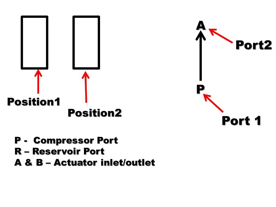
- Ports are designated by alphabets like P,A,B,R,T,X, etc. Their paths which are connected are shown with the help of arrows.
- Position of Directional control valves are represented by square. For each position one square is required. If there are three positions, it means three squares are shown in the symbol.
- Actuation method is shown at the outside of the valve outline represented by the symbol, of actuation method.

Construction and working of various Directional control valves
A) 2/2 D.C. Valve
2/2 means
2 – Two ports (P and A)
2 – Two positions
Construction and Working
- It consists of a valve body in which sliding spool is placed with spool rod.
- The inlet port P and outlet port A are cut in the valve body.
- Spool can be moved with the help of lever, pedal or other actuation method.
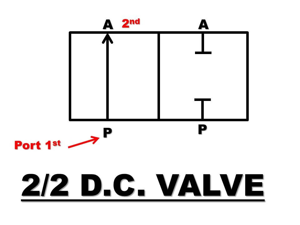
1) Position 1 (P to A)
In this position, the spool is located in the valve such that the port P and A are get connected and oil can easily flow from P A. This position starts the oil supply to the system. It is shown in below fig.
2) Position 2 (P not connect A)
In this position of D.C. valve, the spool is shifted toward left envelop so that the port P get closed and port P and A get disconnected.
The oil will not flow from P to A. This position stops the oil supply to the system.
B) 3/2 D.C. Valve
3/2 means
3 – Three ports (P, A, R)
2 – Two positions a) P A, R closed
b) A R, P closed

Construction and Working
- It consists of sliding spool mounted with spring. The valve body is provided with port P, A and R.
- Position 1 – In this position, the port P and port A is get connected and R port is closed. It will supply the oil to the actuator while flow to the tank port is blocked.
- Position 2 – When spool is shifted, it will block the port P of the pump to stop the supply of pressurized oil to the system. The port A and port R get connected so that oil will drain to the reservoir.
C) 4/2 D.C. Valve
4/2 means
4 – Four ports ( P, A, B, R )
2 – Two positions a) P A, B R
b) A R, P B

- It consists of sliding spool loaded with spring and controlled with the help of suitable method like push button.
- The four ports are provided in the valve body P, A, B, R.
- Position 1 – In this position of D.C. Valve, the spool is placed such that the pump port P get connected to the port A of actuator and port B of actuator is connected to the reservoir port R to drain out the oil.
- Position 2 – In this position, the spool is shifted with the help of push button and spring. Now the port P is get connected port B of actuator and port A of actuator is connected to the reservoir port R to drain out the oil.
Applications
- To operated double acting cylinder
- Bi-directional hydraulic motor in hydraulic system etc.
D) 4/3 D.C. Valve
4/3 means
4 – Four ports ( P, A, B, R )
3 – Two positions a) P to A, B to R
b) P do not connected with A,
B do not connected with R
c) A to R, P to B

Construction and working
Its construction is similar to 4/2 D.C. valve. But it has three positions.
Position1 – It is similar to 4/2 D.C. valve. It connects P to A, B to R.
Position 2 – I t is normal position shown in fig. In this position, the spool is shifted such that port P is closed and oil will not flow from it to the port A or port B. Similarly there is no oil path from port A or B to the reservoir port. It means that all ports of the valves are closed are blocked off. This position called as closed centre position.
Position 3 – It is similar to 4/2 D.C Valve in which connections are A to R, P to B
Applications
It is used to actuate double acting cylinder/Bi-directional hydraulic motor with intermediate stoppage of the cylinder or motor.
D) 5/2 D.C. Valve
5/2 means
5 – Five ports ( P, A, B, R, T)
2 – Two positions a) P to A, B to R, T closed
b) A to T, P to B, R closed
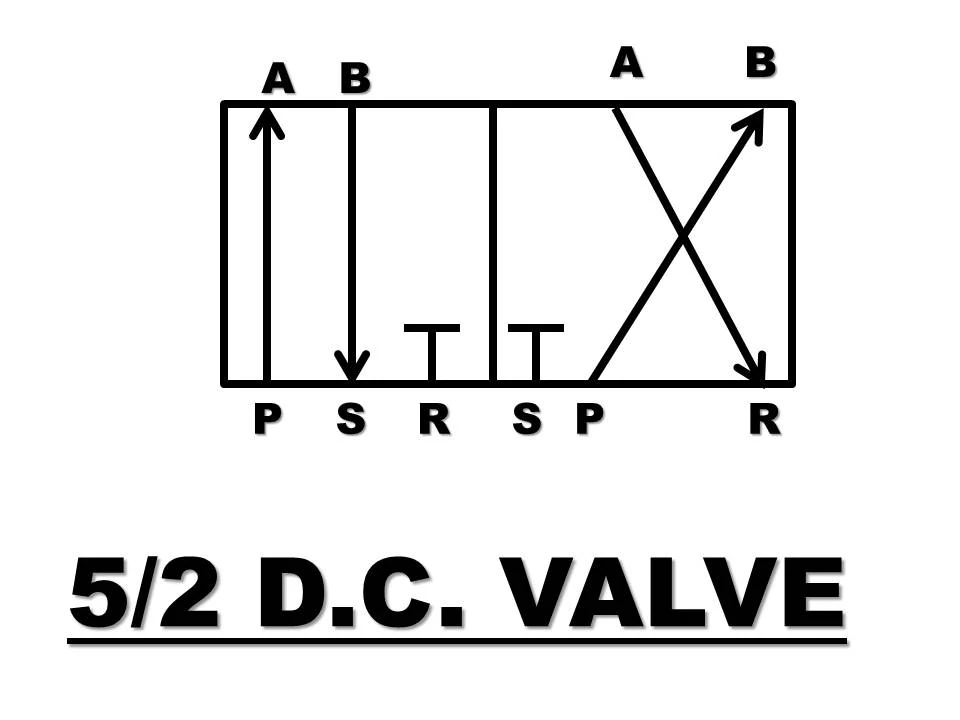
It is sliding spool operated D.C. valve, consists of five ports P, A, B, R and T. T is also reservoir port used independently.
Position 1 – In this position, the spool connects the port P to port A for oil to enter in the system.
While port B to port R to divert flow of used oil to the reservoir, the other reservoir port T is closed.
Position 2 – In this position, the spool connects the port P to port B to enter oil in the system and port A to port T to drain used oil to the reservoir, R port is closed.
You may also like