
Table of Contents
Flow control valve
A flow control valve regulates the flow or pressure of a fluid. Control valves normally respond to signals generated by independent devices such as flow meters.
A flow control valve is a type of valve used in fluid systems to regulate the rate or speed of fluid flow. It is designed to control the flow of a liquid or gas through a pipeline or channel by adjusting the size of the opening or passageway. Flow control valves are commonly used in various industries, including oil and gas, chemical processing, water management, and HVAC (Heating, Ventilation, and Air Conditioning) systems.
The primary function of a flow control valve is to maintain a consistent and desired flow rate within a system. It achieves this by either restricting or increasing the flow of fluid, depending on the application requirements. Flow control valves can be manually operated or automated using actuators and control systems.
Need
To change speed of hydraulic actuators
In hydraulic system, sometimes it is required to increase or decrease the speed of the hydraulic actuator as per application.
1) In hydraulic shaper, the return stroke is faster than the cutting stroke. Hence actuator speed is to be increased during return stroke.
2) Similarly, hydraulic motor is to be operated at various speed toperrform drilling, tapping, operations where speed changing is necessary.
Example – Fig. shows that,when flow port area is increased, it allows more quantity of oil to enter in the actuator and it moves at faster rate. Vice versa, when the flow passage is reduced by flow needle, it allows small quantity of pressurised oil to enter in the actuator and its movement will be at slower rate.
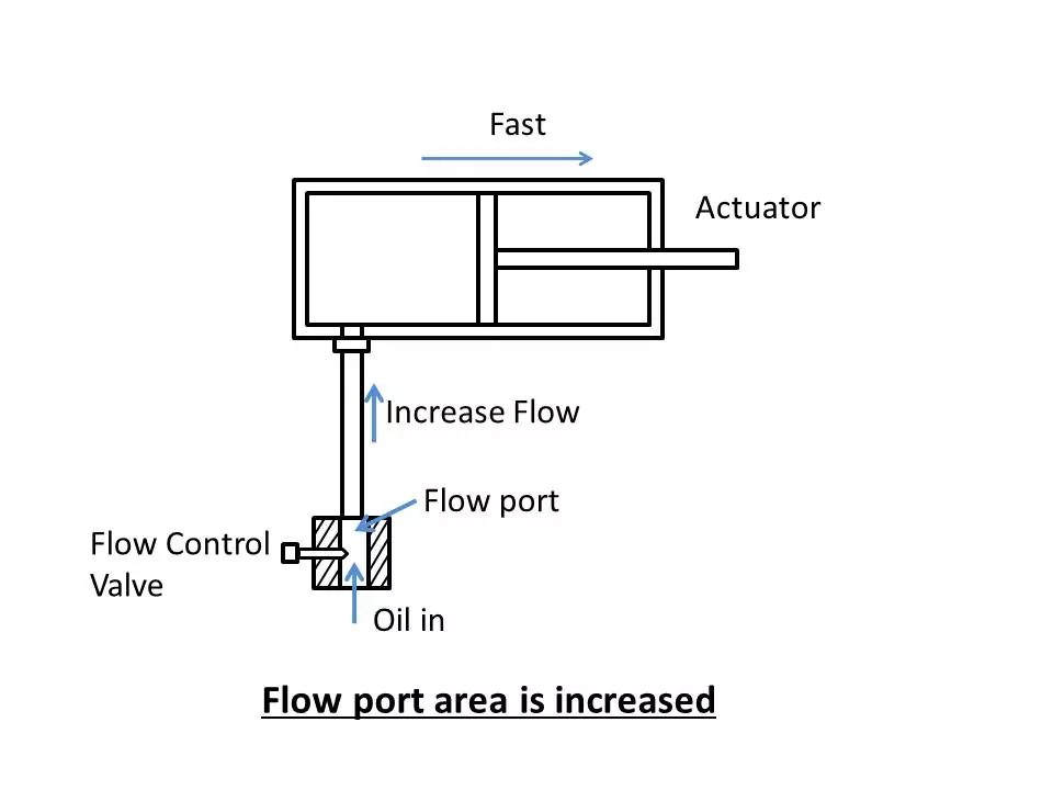

Thus by varing the flow rate (Q) of the oil, we can change the speed of the actuators. This function is performed by flow control valve.
Principle of flow control valve/ Function
The flow rate oil isthe quantity of oil flowing per unit time. It is expressed in lit/min by letter Q.
The flow rate Q and linear cylinder velocity is related by the formula –
V = Q/AWhere V = Cylinder velocity (cm/min)
Q = Flow rate (cm3/min)
A = Area of cylinder piston (cm2)
Similarly rpm of a hydromotor is related by the formula
n = Q/Vwhere V = Volume capacity of motor ( cm3/revolution)
The cylinder velocity (V) and rpm of hydromotor (n) are directly proportional to flow rate (Q). Hence by changing flow rate (Q) we can vary speed ofcylinder and hydromot.
The flow rate can be changed by varying the flow port area.
When a obstruction is inserted in the flow passage like a needle or gate orific, its position in the flow area may increase or decrease the flow quantity of oil passing through it.
Type of FCV
1) Throttle valve – They are two types
a) Fixed throttle
b) Variable throttle (Two way)
2) Pressure dependent flow control valve ( Non compensated)
3) Pressure compensted flow control valve
4) Flow dividers
Location of flow control valve
When the fixed delivery pump is used in hydraulic system.The flow control valve can be located at various points in the system.
a) In between D.C. valve and the actuator
Flow control valve is placed to control flow of oil entering or leaving from the actuator. These are two methods as shown in fig. a and b.
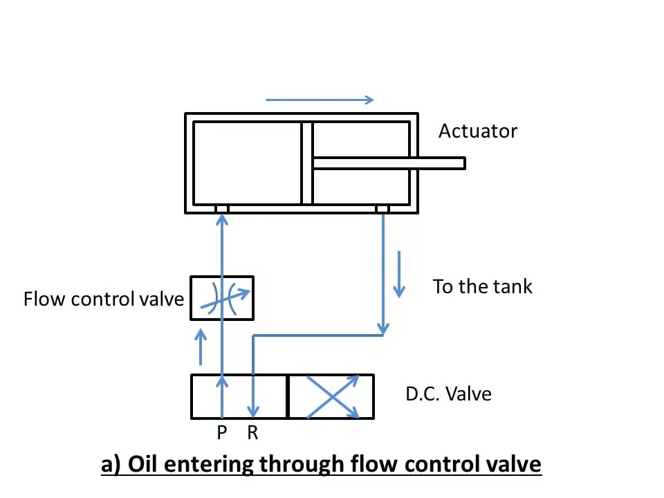
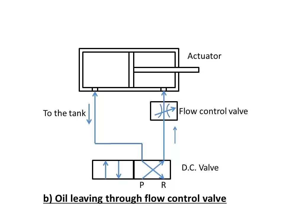
Fig. a shows that flow of oil is controlled when oil enters in the cylinder. This method is called meter-in flow control.
Fig. b shows that flow of oil is controlled while oil leaves the cylinder and drain to the tank. This method is called as meter-out flow control.
b) Between D.C. valve and pump ( By pass arrangement)
In this method, the flow control valve is placed after the pump and some of flow of oil is by pass ( diverted ) to the reservoir. This method is known as bleed-off flow control.

1. Throttle Valve
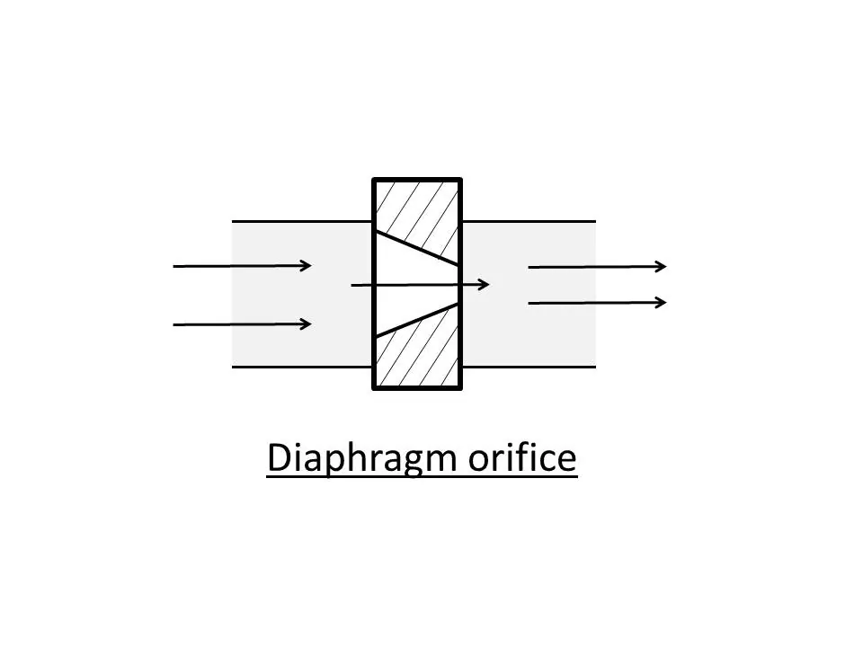
When a small opening is provided to reduce the flow, it causes pressure drop acress the opening called as orifice. It is called as throttle valve.
a) Fixed throttle
In this fixed throttle valve, there is a permanent small aperture (orifice) is providedin the flow direction.
At the throttle aperture,the velocity of oil increases and there is drop in the pressure.
The flow rate at the throttle valve is calculated using the relation.


This throttle valve has constant opening which can not be adjusted. They are generally inserted directly in the pipe lines.
Symbol

b) Diaphragm orifice (throttle)
Two way valve
Symbol
In this type of throttle valve, the needle with pointed end is used for varying the flow opening.

2. NonPressure Compensated Flow Control Valve
When there is no presssure compensation for drop in pressure in the flow control valve, It iscalledas noncompensated flow control valve.
It work on the principle of throttling.
Construction and working

It consists of needle valve fitted with adjustable screw. The needle is the flow control element.
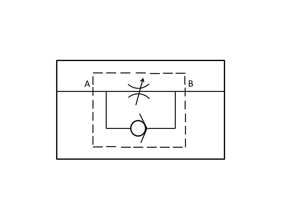
Non return valve is provided along with throttle valve to provide regulated flow in one direction.
This combination is commonly known as flow control valve with inbuilt check valve.
The inlet and outlet port is provided for input of oil supply and regulated flow at the outlet respectively.
The needle position is adjusted to set the throttle opening. The oil flow from the inlet and pass through throttle opening and delivers the required quantity of oil.
At the throttle opening, the reduced passage may cause return flow of oil which is restricted by the check valve fitted near the valve opening.
Application
It is used where pressure is nearlyconstant and monitoring of speed is not critical. It is used in speed control circuits like meter-in, meter-out.
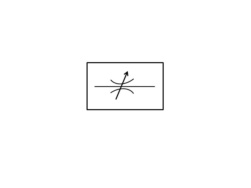
Symbol
3. Pressure Compensated Flow Control Valve
The flow control valve which allows flow control of oil independent of pressure drop and temperature across the valve it is known as pressure compensated flow control valve.
It work on the principle of maintaining a constant pressure drop on the adjustable throttle path with the help of compensating spring loaded spool.
Construction and working
It consists of throttle in the form of needle located in front of inlet port.
The compensator spool is provided with the spring to compensate the drop in pressure across the throttle opening.
The inlet, outlet and other internal passages are provided for all flow in the valve.
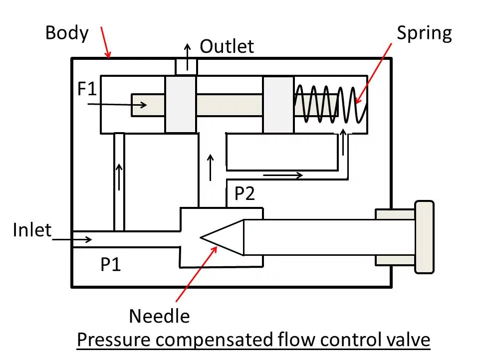
Due to change in the load of actuator, the work resistance also changes and there is a variation in the pressure drop at the entrance and the throttle.
When there is a flow of oil from the inlet, it will flow through two passages,from left hand pilot line it will exert oil pressure on the compensator spool.
Similarly the oil flow from throttle opening and flow from right side pilot line and exerts pressure in addition with spring force.
              Pressure on left side =  Pressure on right side
                          P1. A     =   P2. A + F
                      ( P1 - P2 )A  =   F
                                P   =  F/A = Costant
Where P1 = Pressure before throttling
A = Cross sectional area of valve spool
F = Spring Force
As F and A are both constant P is also constant.
The spring force determines the position of the spool and the amount of oil allowed through the valve.
Application
Precision machine tools and other equipments where constant speed is reqiured independent of external resistanceand temperature.
Symbol

4. Flow Dividers
When the flow of oil is to be divided equally so that it can control the two actuators simultaneously, flow dividers are required.
In this flow control valve,the oil flow is divided equally as shown in fig.

It is used in motion synchronisation of hydraulic actuators like lifting of load at same speed by two cylinders.
Symbol

What is Flow Control Valve – Principle, Need, Type, Symbol
Advantages and Disadvantages of Flow Control Valve
Flow control valves are essential components in fluid systems, regulating the rate at which a fluid (liquid or gas) flows through a pipeline. They are used in various industries and applications. Here are the advantages and disadvantages of flow control valves:
Advantages
Flow Regulation:
Precise Control: Flow control valves allow for precise regulation of fluid flow rates, ensuring that the system operates at the desired levels.
System Stability:
Stable Operations: By adjusting the flow, these valves contribute to the stability of a system, preventing fluctuations and maintaining consistent performance.
Energy Efficiency:
Energy Conservation: Flow control valves can be used to optimize energy consumption by adjusting flow rates based on system requirements, leading to energy efficiency.
Process Optimization:
Optimized Processes: In industrial processes, flow control valves enable optimization and fine-tuning of various stages, improving overall efficiency and productivity.
Prevention of Damage:
Protection Against Overflows: Flow control valves prevent overflows and excessive pressure in the system, protecting equipment and preventing potential damage.
Versatility:
Adaptability: Flow control valves are available in various types and configurations, making them versatile for different applications and industries.
Remote Control:
Automation Capability: Many flow control valves can be integrated into automated systems, allowing for remote control and operation.
Disadvantages
Pressure Drop:
Energy Loss: Flow control valves can introduce pressure drops in the system, leading to energy losses. This is especially true when the valve is partially closed.
Cavitation and Erosion:
Potential Damage: Improper use or extreme conditions may lead to cavitation and erosion, causing damage to the valve and other system components.
Maintenance Requirements:
Regular Maintenance: Flow control valves require regular maintenance to ensure proper functionality and prevent issues like sticking or leakage.
Initial Cost:
High Initial Investment: High-quality flow control valves can be expensive, especially those designed for specialized applications, increasing the initial cost of the system.
Complexity:
Complex Systems: In some cases, the integration and control of flow control valves may add complexity to the overall system, requiring a more sophisticated control strategy.
Size and Weight:
Bulkiness: Some flow control valves, particularly those with larger diameters, can be bulky and heavy, requiring adequate space and support in the system.
Material Compatibility:
Material Considerations: Selection of the appropriate material for the valve is crucial to avoid corrosion and ensure compatibility with the fluid being handled.
What is Flow Control Valve – Principle, Need, Type, Symbol
Application of Flow Control Valve
Flow control valves find applications in a wide range of industries and systems where precise regulation of fluid flow is essential.
Some common applications of flow control valves:
Water and Wastewater Treatment:
Flow control valves are used in water treatment plants to regulate the flow of water through various stages of the treatment process, ensuring that each stage operates at optimal conditions.
Oil and Gas Industry:
In the oil and gas industry, flow control valves are employed to regulate the flow of oil, gas, and other fluids through pipelines, helping to control pressure and optimize production processes.
Chemical Processing:
Flow control valves play a crucial role in chemical processing plants where precise control of fluid flow is necessary to maintain the desired reaction rates and avoid unwanted reactions.
HVAC Systems:
Heating, ventilation, and air conditioning (HVAC) systems use flow control valves to regulate the flow of air or water through pipes and ducts, ensuring proper temperature control and energy efficiency.
Automotive Industry:
Flow control valves are integrated into automotive systems, such as engine coolant systems and hydraulic brake systems, to regulate the flow of fluids and optimize performance.
Pneumatic Systems:
Flow control valves are used in pneumatic systems to regulate the flow of compressed air, controlling the speed and force of pneumatic actuators in various industrial applications.
Food and Beverage Processing:
In the food and beverage industry, flow control valves are employed to regulate the flow of liquids, such as ingredients and cleaning solutions, in processing and packaging operations.
Aerospace Industry:
In aircraft and spacecraft, flow control valves are used in hydraulic and fuel systems to regulate the flow of fluids, ensuring the proper functioning of critical components.
FAQ’s
What is the basic principle of control valve?
Control valves work by measuring pressure or flow on each side of a valve and then regulating these pressures through the use of an actuator or other method. This adjustment can be done manually or automatically depending on the type of valve and its settings.
What type of valve is used for flow control?
A typical example of a flow control valve is the simple water faucet installed in homes. Globe valves and needle valves are standard designs used for flow control. One-way flow control valves control flow in one direction but allow free flow in the other direction.
You may also like