
Table of Contents
What is Hydraulic Valve
In a general layout of hydraulic system, after pump the next immediate important components are located which are control Valve. They are placed in between pump and actuators.
The pump ganerates flow of oil which is fed to the actuators through a controlling elements known as valves. Hence valve is nothing but a device which controls the oil energy.
” Hydraulic Valve is a mechanical device which controls the oil energy as per requirement of the system.”
Need of Hydraulic Valve
The valves are fluid controllingelement which has to perform following functions –
a) Direction of flow –
The oil is to be fed to the inlets of the actuators to obtain output motion. Hence flow direction is to be changed.
b) Pressure of oil –
Pressure is to be reduced or excess pressure is to be relived using control valves.
c) Flow quantity –
To increase/decrease flow of oil to vary the speed of actuator.
d) Blocking/Stopping of flow of oil –
When the oil supply is not required to the other part of the hydraulic system.
e) Special function –
It includes flow of oil in only one direction, diverting flow of oil.
Classification Of Hydraulic Control Valve
| Control parameter | Function | Type |
| 1. Oil Pressure | To increase/decrease the oil pressure as per requirement of the hydraulic system. | Pressure Control Valve a) Pressure relief valve b) Pressure reducing valve c) Unloading valve d) Sequence valve |
| 2. Flow or quantity of oil | To control flow of oil to obtain variable speed of the actuators in the hydraulic system. | Flow Control Valve a) Pressure compensated valve b) Non pressure compensated valve c) Two way valves d) Throttle valve |
| 3. Direction of oil feed | To change the oil feed path to obtain output motion of cylinder/motor of hydraulic system. | Direction Control Vlave a) 2/2 D.C. Valve b) 3/2 D.C. Valve c) 4/2 D.C. Valve d) 4/3 D.C. Valve e) 5/3 D.C. Valve f) Pilot operated D.C. Valve |
Pressure Control Valve
Need of pressure control valve
- To relief the excessive pressure if oil pressure is greater than working pressure of the system
When working pressure is exceeded by the pump oil pressure, it may cause hazards and damaze of pipe lines and other components hence as a safety device, pressure relief valves are provided.
- Regulating and reducing pressure in certain portions of the circuit
When actuator 1 is requires pressure of 30 bar while actuator is operating at pressure of 15 bar. In this cause, the pressure of oil is to be reduced from30 bar to 15 bar. This function is performed by pressure reducing valve.
- To achieve sequential operation of actuators in circuit with pressure control
When the number of actuators are to be operated one after another in a sequence, with the help of pressure control, sequence valve of pressure control is used.
- Unloading system pressure
When it is required to unload the pressure to save the system from undesired heat energy. This function is performed by unloading valve.
Type of pressure control valve
Pressure control valves are classified according to their function, type of connection, size and pressure operating range.
| Type | Application |
| 1. Pressure relief valve | To relieve excessive pressure in the system |
| 2. Pressure reducing valve | To reduce pressure of oil in certain portain of circuit |
| 3. Unloading valve | Unloading the pressure in the system |
| 4. Sequence valve | To actuate actuators in a sequence |
Pressure Relief Valve
When pressure control valve is used to limit the pressure in a system to a prescribed maximum value by draining some or all the pump output to the reservoir tank when desined set pressure is reached, it is known as Pressure relief valve.
It work on the principle of lifting the valve element with oil pressurea gainst the spring set pressure. When set pressure is greater than oil pressure,the valve is closed and opens when oil pressure exceeds the set pressure.
Type of pressure relief valve
- Direct Operated Pressure Relief Valve
It consists of following main –
- Pressure setting knob – It is a screw which can be adjusted to set the spring force as per requirement.
- Spring – It is provided to set the designed pressure of the hydraulic system with the help of setting knob.
- Poppet – It is the main valve component of conical shape seated in the valve body. Its upper end is attached to the spring which exerts compressive force on it.
- Valve body – It is provided with the inlet and drain ports and accommodate all above components.
Working
- It is normally closed valve connected between pressure presssure line and the oil reservoir. When inlet oil pressure is less than the spring force, it means that it is insufficient to overcome the spring force, the valve remain closed. The pressure of oil is safe for the sytem.
- When the oil pressure is greater than spring force, it pushes the poppet against the spring force and unseated the poppet. Now the valve open and oil flow from inlet port to the reservoir. The valve will remain open until the excessive pressure is diverted to the tank.
- It is essential for every hydraulic system to provide pressure relief valve as a safegauard against the pressure override.
Limitations
- They are suitable where the flow rate and the system are reasonably smaller.
- There is no much variation in system pressure of flow rate.
- It is not feasible to use bigger spring due to more space requirement for higher system pressure.
What is Hydraulic Valve – Type, Working, Application, More
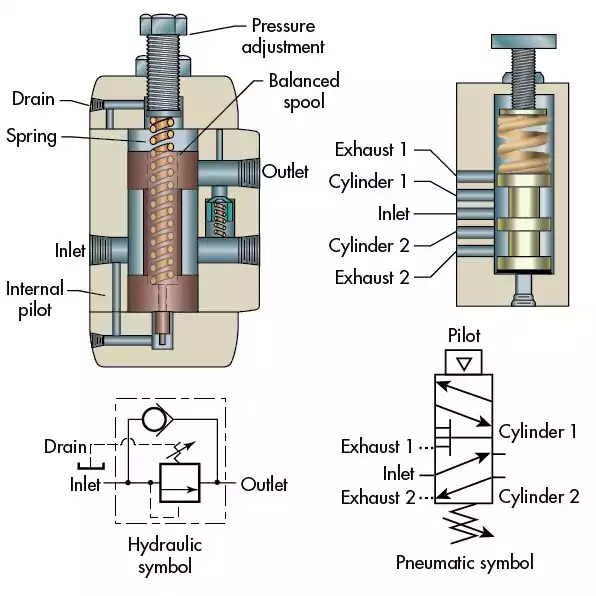
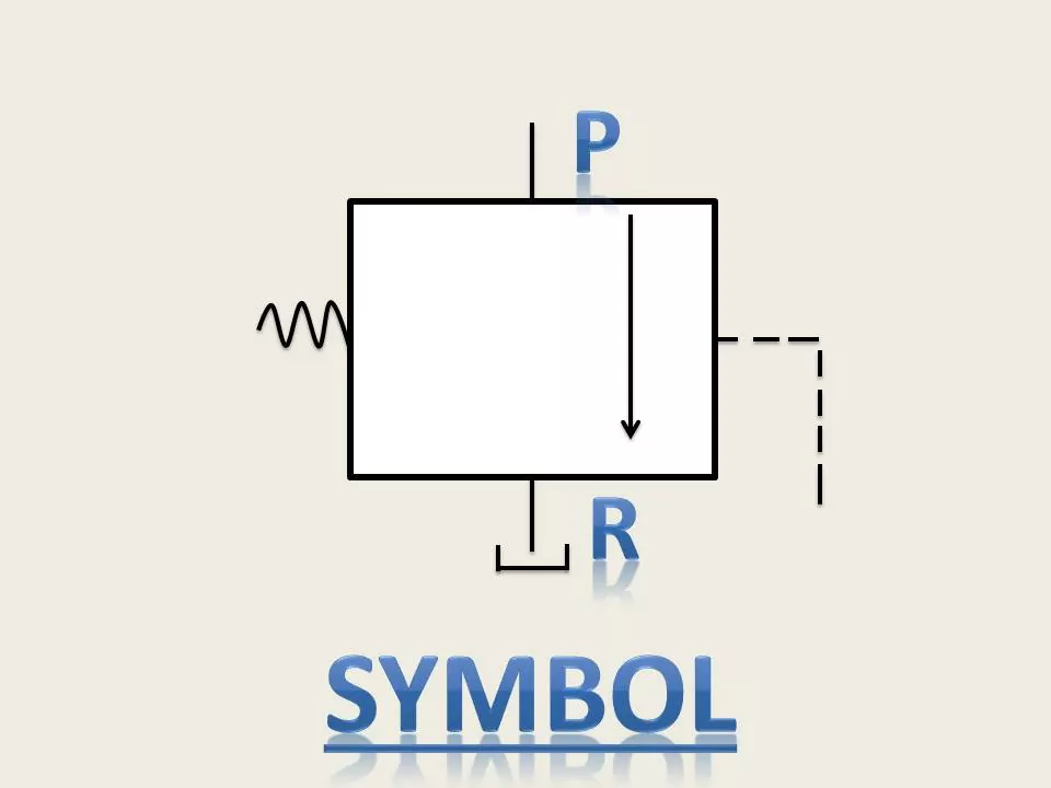
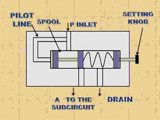
Pilot Operated Pressure Relief Valve
when the valve element is actuated indirectly through the internal pilot line to relief the excessive pressure it is known as pilot operated pressure relief valve.
It works on the principle of throttling by orifice produced in the main spool which operates the valve element using spring and throttle oil pressure.
It consists of
- Mian spool – The main spool is seated with the help of spring force and it is provided with orifice.
- Poppet and spring – It is provided as a second stage pressure controlling element which is connected with the of pilot line. The spring is used to seat the poppet.
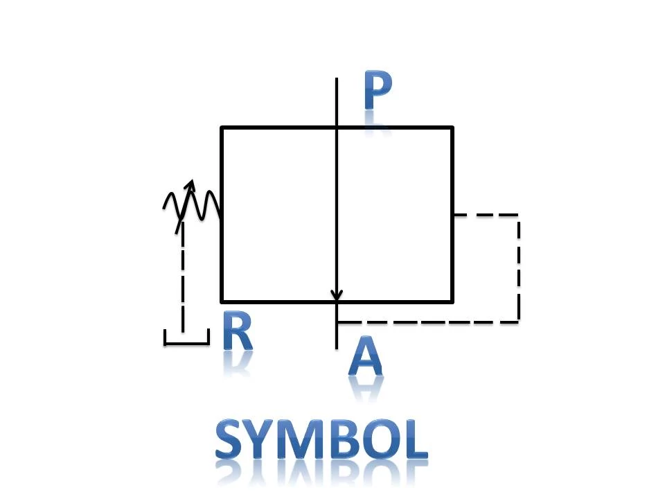
- Port P and Port R – They are provided for inlet and diverting flow to the tank.
- Adjusting screw – It is provided to vary the pressure setting.
Working
Oil will enter through the main port P and passed through orifice in the main valve spool.
When it flow through the orifice, there is a pressure drop due to throttling effect. If the pressure of the oil is less than the set pressure the valve will remain in closed position.
However, if there is increase in pressure due to some reasons, the throttle valve of a pressure in the chamber above main spool will also change to a higher value and thus act against the poppet through the pilot line.
As oil pressure is higher it will lift the poppet and creates pressure difference between throttled oil pressure and supply oil pressure. The main spool automatically moves up to open port P to port R. So that oil will be drain out to the tank.
Pressure Reducing Valve
When a pressure control valve is provided to maintain a constant pressure to a part of system that is lower than the pressure in the rest of the system. It is known as pressure reducing valve.
It is normally open type valve, which utilizes the spool movement to reduce the pressure by partly blocking outlet port.
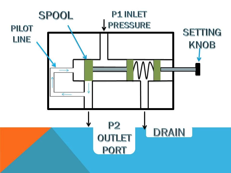
It consists of following main parts
- Setting knob – It is provided for setting of valve as per requirement of pressure.
- Pilot line – Pilot line is provided to control the movement of sliding spool.
- Inlet and Outlet ports are provided in a valve body with a drain for leakage of oil.
- Sliding spool – It is a main valve element which is mounted with the help of spring.
Working
Normally open position –
When the main supply pressure at the inlet is below the valve setting, the fluid will flow freely from the inlet to the outlet. The valve will remain open.
Actuating position –
When inlet pressure is greater, the oil will flow from the outlet passage through internal pilot line and cats on the sliding spool to oppose the spring force.
When outlet pressure rises to the valve setting, the spool moves to partly block the outlet port. Now only enough flow is passed to the outlet to maintain preset pressure and reduced pressurized oil is supplied to the system.
Unloading Valve
As you see it’s name indicates, when pressure control valve is used to unload the oil energy at a low pressure to save energy, it is called unloading valve.
It is spool operated valve which is actuated through external pilot line and unload the pressurised oil from pump.
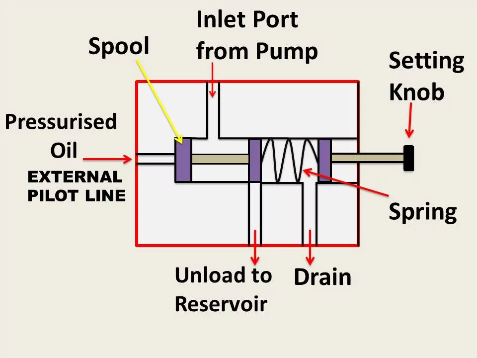
Construction and working
It consists of sliding spool mounted with the help of spring. The spring force is set with the help of setting knob or screw. The external pilot line is provided through which spool is pushed up, against the spring force.
The pump port P and the unloading port R is provided. When it is required to unload the pressuer from the pump the oil is allowed to enter through pilot line and lifts the spool in the upward direction.
Now the port P and port R get connected and oil will go to the reservoir to unload the pump.
This unloading valve is generally located before the pressure relief valve. The advantages of unloading valves are it helps to reduce heat energy to a great extent and used in systems where two pumps provide a large volume of oil at low pressure and one of them must be unloaded a specific period.
Sequence Valve
When a pressure control valve is placed in a such manner that it will actuate the operation in a sequence one after another, it is called as sequence valve .
It is spool operated valve in which internal pilot line is used to build up pressure to actuate the sub circuit in a sequence.
Construction And Working
The sequence valve consists of spring loaded spool, setting screw knob, valve body with inlet port, port for sub circuit and drain port.
The internal pilot line is provided to operate the spool. Drain is provided for any internal leakage of oil.
This valve is mainly placed in the oil path of two actuators where sequence is desired. When the first actuator completes it operation, the oil will flow towards the inlet of the sequence valve.
It will enter in the pilot line and exerts a pressure from bottom side of the spool. The spool moves upward when sufficient pressure is build up and connects inlet port to the subcircuit port to supply oil to the another actuator.
Example of sequence operation
In this exmple, there are two operations first one is clamping of job with hydraulic cylinder and second one is drilling in work piece.
The sequnce valve is used to actuate sequence of clamping and drilling.
In this first clamping is done by hydraulic cylinder and it hold workpiece firmly, then buildup pressure will open the sequence valve and rotates the hydraulic rotor for drilling.

Application
- Sequence valve can be used for movement of material from one location to another location.
- It is used for machining and clamping of workpiece.
- Sequence valve are commonly used in pressure dependent sequencingcircuits.
Advantages and Disadvantages of Hydraulic Valve
Hydraulic valves play a crucial role in controlling the flow and pressure of hydraulic fluids in various applications, such as industrial machinery, construction equipment, and automotive systems. Here are some advantages and disadvantages of hydraulic valves:
Advantages
Precise Control: Hydraulic valves provide precise control over the flow and pressure of hydraulic fluids, allowing for accurate and efficient operation of machinery.
High Power Density: Hydraulic systems can deliver high power density, meaning they can transmit a large amount of power with relatively small and lightweight components.
Versatility: Hydraulic valves are versatile and can be used in a wide range of applications, from heavy machinery to delicate precision equipment.
Instantaneous Response: Hydraulic systems offer quick and precise response times, making them suitable for applications that require rapid and accurate adjustments.
High Torque at Low Speeds: Hydraulic systems are well-suited for applications that require high torque at low speeds, such as in construction equipment.
Reliability: Hydraulic systems are known for their reliability and durability, especially in demanding and harsh environments.
Disadvantages
Fluid Leakage: One of the common issues with hydraulic systems is the potential for fluid leakage, which can lead to environmental concerns and maintenance challenges.
Maintenance Requirements: Hydraulic systems require regular maintenance to ensure proper functioning. This includes checking for leaks, replacing seals, and monitoring fluid levels.
Temperature Sensitivity: Hydraulic fluids can be sensitive to temperature changes, and extreme temperatures can affect the performance of the system. Cooling systems may be required to address this issue.
Complexity: Hydraulic systems can be complex, requiring skilled technicians for installation, troubleshooting, and maintenance. This complexity can also lead to higher initial costs.
Energy Efficiency: While hydraulic systems are powerful, they may not be as energy-efficient as some other systems, especially in applications where precise control and energy conservation are critical.
Noise: Hydraulic systems can produce noise, especially at higher pressures and flow rates. Noise reduction measures may be necessary in certain applications.
Hydraulic valves offer precise control and high power density but come with challenges such as fluid leakage, maintenance requirements, and complexity. The choice to use hydraulic valves depends on the specific requirements of the application and the trade-offs that can be accepted.
Applicationof Hydraulic Valve
Hydraulic valves find application in a wide range of industries and systems where the control of fluid flow and pressure is essential.
Some common applications of hydraulic valves:
Industrial Machinery:
Hydraulic valves are widely used in industrial machinery, including presses, plastic molding machines, and metal forming equipment, to control the movement of actuators and perform various tasks.
Construction Equipment:
Hydraulic valves play a crucial role in construction machinery such as excavators, bulldozers, and cranes. They control the movement of hydraulic cylinders and motors for tasks like lifting, digging, and maneuvering.
Aerospace Industry:
Hydraulic systems are utilized in aircraft for functions like landing gear deployment, flap movement, and brake systems. Hydraulic valves contribute to the precise control of these critical functions.
Automotive Industry:
Hydraulic valves are used in various automotive systems, including brake systems (hydraulic brakes), power steering systems, and transmission control systems. They help control the flow of hydraulic fluid for efficient and safe vehicle operation.
Oil and Gas Industry:
Hydraulic valves are employed in oil and gas exploration and production equipment. They are used in systems for controlling drilling equipment, pipeline valves, and other hydraulic-powered machinery.
Marine Applications:
Hydraulic valves are used in marine systems for tasks such as controlling ship stabilizers, steering systems, and winches. They provide precise control in demanding marine environments.
Mining Equipment:
Mining machinery, such as excavators, haul trucks, and drilling rigs, often relies on hydraulic systems for efficient and powerful operation. Hydraulic valves control the movement of various components in these machines.
Material Handling:
Hydraulic valves are essential in material handling equipment, such as forklifts and conveyor systems. They control the movement of lifting mechanisms and other components.
Automation and Robotics:
Hydraulic systems with valves are employed in industrial automation and robotics for precise and controlled movement of robotic arms and other automated machinery.
FAQ’s
What is the principle of hydraulic valve?
A hydraulic valve properly directs the flow of a liquid medium, usually oil, through your hydraulic system. The direction of the oil flow is determined by the position of a spool. A hydraulic system can only function – as per requirements – by using valves.
Where are hydraulic valves used?
Hydraulic valves are mechanical devices that are used to regulate the flow of fluid within a hydraulic circuit or system. They can be used to completely close a line, to redirect pressurized fluid or to control the level of flow to a certain area.
You may also like