
Table of Contents
Gears
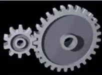
Gears are toothed wheels used for transmitting motion and power from one shaft to another shaft when they are not too far apart and when a constant velocity ratio is desired.
A gear may be a quite machine element during which teeth are cut around cylindrical or cone shaped surfaces with equal spacing. By meshing a pair of those elements, they’re wont to transmit rotations and forces from the driving shaft to the driven shaft. Gears are often classified by shape as involute, cycloidal and trochoidal gears. Also, they will be classified by shaft positions as parallel shaft gears, intersecting shaft gears, and non-parallel and non-intersecting shaft gears.
Principle of Gears
Gears are mechanical elements that transmit motion and power between rotating shafts. They are widely used in various machines and mechanisms to achieve specific functions such as speed reduction, torque amplification, or direction reversal. The principles of gears are based on their fundamental characteristics and interactions. Here are some key principles of gears
Transmission of Motion
Gear transmit rotational motion from one shaft to another. When two gears mesh, the teeth of one gear engage with the teeth of the other, causing the second gear to rotate.
Speed Ratio
The speed ratio between two meshing gear is determined by the ratio of their numbers of teeth. If a small gear (pinion) with fewer teeth meshes with a larger gear (gear), the speed of the driven gear will be reduced, but the torque will be increased.
Speed Ratio = Number of Teeth on Driven Gear / Number of Teeth on Driving Gear
Direction of Rotation
The direction of rotation can be reversed by using an odd number of gears in the transmission. If an even number of gears are used, the rotation direction remains the same.
Torque Transmission
Gears also transmit torque. The torque ratio between two meshing gears is inversely proportional to their speed ratio. If the speed is reduced, the torque is increased, and vice versa.
Torque Ratio = Speed Ratio = (Number of Teeth on Driven Gear / Number of Teeth on Driving Gear)
Interference and Backlash
Interference occurs when gear teeth interfere with each other’s paths during rotation. Backlash is the clearance between the meshing teeth, and it is essential to prevent binding and ensure smooth operation.
Gear Train
A combination of gears arranged in series is called a gear train. Gear trains are used to achieve specific speed and torque relationships.
Radius of a Gear
The radius of a gear, also known as the pitch radius, is a crucial parameter in gear design. The pitch radius is the distance from the center of a gear to the point where the teeth mesh with another gear. It is half of the gear’s pitch diameter
The pitch diameter (D) of a gear is the diameter of the imaginary pitch circle that the gear tooth profile is based on. The pitch radius (R) is then calculated as:
R = D/2
In gear systems, the pitch diameter is a fundamental dimension used to determine the gear ratio, tooth profile, and other characteristics. The pitch radius is important for calculating the rotational speed and angular velocity of the gear, as well as for understanding the geometric relationships between meshing gears.
Classification of gear
Gears are classified as
1) Gears with parallel axes
a) Spur gear
b) Helical gear
c) Rack and pinion gear
d) Double helical or herringbone gear
2) Gear in which the shaft axes intersects if prolonged
a) Bevel gear
b) Spiral bevel gear
3) Gears in which the axes are neither parallel nor intersecting
a) Worm gear
b) Hypoid gear
Spur gear
Gears having cylindrical pitch surfaces are called cylindrical gears. Spur gears belong to the parallel shaft gear group and are cylindrical gears with a tooth line which is straight and parallel to the shaft. Spur gears are the foremost widely used gears which will achieve high accuracy with relatively easy production processes. They have the characteristic of getting no load within the axial direction (thrust load). The larger of the meshing pair is named the gear and smaller is named the pinion.
Helical gear
Helical gears are used with parallel shafts almost like spur gears and are cylindrical gears with winding tooth lines. They have better teeth meshing than spur gears and have superior quietness and may transmit higher loads, making them suitable for top speed applications. When using helical gears, they create thrust force within the axial direction, necessitating the utilization of thrust bearings. Helical gears accompany right and left twist requiring opposite hand gears for a meshing pair.

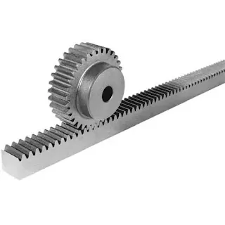
Rack and pinion gear
Same sized and shaped teeth cut at equal distances along a flat surface or a straight rod is named a rack and pinion gear. It is cylindrical gear with the radius of the pitch cylinder being infinite. By meshing with a cylindrical gear pinion, it converts rotational motion into linear motion. Gear racks are often broadly divided into straight tooth racks and helical tooth racks, but both have straight tooth lines. By machining the ends of drugs racks, it’s possible to attach gear racks end to finish .
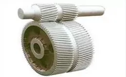
Double helical or herringbone gear
Herringbone gears are a special sort of helical gears. A double helical gear are often thought of as two mirrored helical gears mounted closely together on a standard axle. This arrangement cancels out the axial thrust, since each half the gear thrusts within the other way , leading to a net axial force of zero. This arrangement also can remove the necessity for thrust bearings. However, double helical gears are harder to manufacture due to their more complicated shape.
Bevel gear
Bevel gears have a cone shaped appearance and are wont to transmit force between two shafts which intersect at one point (intersecting shafts). A pinion and crown wheel features a cone as its pitch surface and its teeth are cut along the cone.

Spiral bevel gear
Spiral bevel gears are bevel gears with curved tooth lines. With higher tooth contact ratio, they’re superior to straight bevel gears in efficiency, strength, vibration and noise. On the opposite hand, they’re harder to supply . Also, because the teeth are curved, they cause thrust forces within the axial direction. Within the spiral bevel gears, the one with the zero twisting angle is named zerol pinion and crown wheel .

Worm gear
A screw shape cut on a shaft is that the worm, the mating gear is that the gear , and together on non-intersecting shafts is named a gear . Worms and worm wheels aren’t limited to cylindrical shapes. there’s the hour-glass type which may increase the contact ratio, but production becomes harder . thanks to the sliding contact of the gear surfaces, it’s necessary to scale back friction. For this reason, generally a tough material is employed for the worm, and a soft material is employed for gear . albeit the efficiency is low thanks to the sliding contact, the rotation is smooth and quiet. When the lead angle of the worm is little , it creates a self-locking feature.

Hypoid gear
Hypoid gear resemble spiral bevel gears except the shaft axes don’t intersect. The pitch surfaces appear conical but, to catch up on the offset shaft, are actually hyperboloids of revolution.
Hypoid gears are nearly always designed to work with shafts at 90 degrees.
Counting on which side the shaft is offset to, relative to the angling of the teeth, contact between hypoid gear teeth could also be even smoother and more gradual than with spiral pinion and crown wheel teeth, but even have a sliding action along the meshing teeth because it rotates and thus usually require a number of the foremost viscous sorts of gear oil to avoid it being extruded from the mating tooth faces, the oil is generally designated HP (for hypoid) followed by variety denoting the viscosity.
Also, the pinion are often designed with fewer teeth than a spiral bevel pinion, with the result that gear ratios of 60:1 and better are feasible employing a single set of hypoid gears.

Gear Design
Designing gear involves creating the shapes and dimensions of the tooth profile and other features to ensure proper functionality and performance. Gears are essential components in machinery, transmitting motion and power between shafts.
Basic steps involved in gear design:
Determine Requirements
Understand the application and requirements of the gear, such as speed, torque, power, and environmental conditions.
Select Gear Type
Choose the appropriate gear type based on the application. Common types include spur gears, helical gears, bevel gears, worm gears, etc.
Calculate Gear Parameters
Use mathematical equations to calculate essential gear parameters such as pitch diameter, pitch, module, pressure angle, and number of teeth. These parameters depend on the specific gear type and application.
Check Design Constraints
Verify that the gear design meets specific constraints, such as space limitations, weight limitations, and manufacturing capabilities.
Determine Gear Ratio
Define the required gear ratio based on the application’s needs. This ratio influences the speed and torque relationship between the driving and driven gears.
Tooth Profile Design
Design the tooth profile based on the selected gear type. This involves determining the shape of the teeth, such as involute for most spur and helical gears.
Calculate Tooth Dimensions
Calculate the dimensions of individual teeth, including addendum, dedendum, clearance, and fillet radii. These dimensions ensure proper meshing and load distribution.
Check for Interference
Verify that there is no interference between mating gears during rotation. This involves checking for collisions between gear teeth and modifying the design if necessary.
Material Selection
Choose appropriate materials for the gears based on factors like strength, wear resistance, and durability.
Manufacturability Considerations
Ensure that the gear design is manufacturable using common manufacturing processes like hobbing, milling, or grinding. Consider tolerances and other factors relevant to the chosen manufacturing method.
CAD Modeling
Create a detailed Computer-Aided Design (CAD) model of the gear using software tools. This model should accurately represent the gear’s geometry.
Analysis and Simulation
Perform stress analysis and simulation to ensure that the gear can withstand the expected loads and conditions. This step helps identify potential failure points and allows for optimization.
Prototype and Testing
Build a prototype of the gear and conduct testing to validate the design’s performance. This step may involve making adjustments to the design based on test results.
Documentation
Document the gear design, including specifications, drawings, and any relevant analysis results. This documentation is essential for manufacturing and future reference.
Manufacturing
Once the design is finalized, proceed with the manufacturing process, whether it involves machining, casting, or other methods.
Mechanism of Gears
Gears are mechanical devices with teeth that mesh with one another to transmit power and motion. They are essential components in many machines and mechanisms, playing a crucial role in transforming rotational motion, changing torque, and altering the direction of rotation.
The mechanism of gears involves several key concepts:
Teeth and Pitch Diameter
Gears have teeth that are designed to mesh with each other. The size and shape of these teeth are crucial for the proper functioning of the gears.
The pitch diameter is an imaginary circle that represents the effective size of the gear and is used in calculations for gear ratios.
Gear Ratio
The gear ratio is the ratio of the number of teeth on one gear to the number of teeth on another gear in a meshing pair. It determines how the rotational speed and torque are transformed between gears.
Gear ratio = Number of teeth on driven gear / Number of teeth on driving gear
Types of Gears
Spur Gears: The most common type, with straight teeth that are parallel to the gear axis.
Helical Gears: Have angled teeth, resembling the shape of a helix. They provide smoother operation and less noise compared to spur gears.
Bevel Gears: Have teeth that are conically shaped, used to transmit motion between intersecting shafts.
Worm Gears: Consist of a screw (worm) and a mating gear (worm gear). They provide high torque but have low efficiency.
Gear Train
A gear train is a combination of two or more gears working together to transmit motion and power. The arrangement of gears in a train affects the overall gear ratio.
Direction of Rotation
The direction of rotation is determined by the arrangement of gears in a system. Meshing gears with the same direction of helix result in the same direction of rotation, while opposite helix directions result in reversed rotation.
Torque and Speed
Gears can be used to trade-off between torque and speed. Larger gears (more teeth) provide higher torque but lower speed, while smaller gears (fewer teeth) offer higher speed but lower torque.
Meshing and Contact
Proper meshing of gear teeth is essential for efficient power transmission. The teeth should be designed to ensure smooth and continuous contact without jamming or slipping.
Materials Used in Gears
Gears are mechanical components used to transmit power and motion between shafts in various machines and mechanisms. The materials used in gears depend on the specific application, load requirements, and environmental conditions.
Some common materials for gears include:
Steel:
Carbon Steel: Commonly used for industrial gears due to its strength and durability.
Alloy Steel: Provides better strength and wear resistance compared to carbon steel.
Cast Iron:
Gray Iron: Offers good wear resistance and dampens vibration, suitable for low to moderate load applications.
Ductile Iron: Has enhanced strength and toughness compared to gray iron.
Stainless Steel:
Corrosion-resistant and durable, making it suitable for gears in environments where corrosion is a concern.
Bronze:
Phosphor Bronze: Known for its self-lubricating properties, making it suitable for gears without external lubrication.
Aluminum Bronze: Combines strength with corrosion resistance.
Brass:
Commonly used in low-load and low-speed applications, where its low friction and wear characteristics are beneficial.
Plastics:
Nylon: Offers self-lubricating properties and is often used in applications where noise reduction is important.
Polyacetal (Delrin): Provides good strength and low friction.
Polyethylene: Used in low-load, low-speed applications.
Ceramics:
Silicon Nitride, Zirconia: High-strength materials used in specialized applications where extreme hardness and wear resistance are required.
Powdered Metals:
Powdered Metal Alloys: Used in powder metallurgy processes to create gears with enhanced properties.
Backlash in Gear
Backlash refers to the clearance or play between mating gear teeth. It is a crucial consideration in gear design and is necessary to prevent binding and ensure smooth operation. Backlash allows for slight movements between gears, which is important for accommodating manufacturing variations, thermal expansion, and other factors.
Excessive backlash can result in reduced precision and responsiveness in mechanical systems, while too little backlash can lead to increased wear and the potential for binding. Properly managing backlash is important in applications where precision and reliability are critical, such as in robotics, automotive transmissions, and other mechanical systems.
Difference between a gear and a sprocket
Gears and sprockets are both mechanical components used in various machines and systems, but they serve different purposes and have distinct characteristics.
Key differences between gears and sprockets:
Function
Gears: Gears are mechanical components with toothed wheels that mesh together to transmit motion and power. They are used to transfer rotational motion and torque between shafts, changing the speed and direction of the motion.
Sprockets: Sprockets, on the other hand, are specialized gears used in conjunction with a chain. They are primarily employed for transmitting motion and power between rotating shafts, usually in applications such as bicycles, motorcycles, or industrial machinery.
Tooth Shape
Gears: Gears can have various tooth shapes, such as involute, cycloidal, or helical, depending on the specific application and design requirements.
Sprockets: Sprockets typically have teeth designed to match the pitch of the chain with which they are used. The teeth are usually simple and designed to engage with the links of a chain.
Usage
Gears: Gears are commonly used in a wide range of applications, including automobiles, machinery, clocks, and more. They are versatile and can be employed in systems where precise speed control and torque transmission are crucial.
Sprockets: Sprockets are often used in systems that require the transfer of motion and power through a chain, such as bicycles, motorcycles, conveyors, and some industrial machinery.
Connection
Gears: Gears can mesh directly with each other or be connected through an intermediate shaft to transmit motion. They may also be part of a gear train, where multiple gears work together.
Sprockets: Sprockets are typically connected to shafts or axles using a key, set screws, or other means. They work in conjunction with a chain, and the engagement of the chain with the sprocket’s teeth allows for the transmission of motion.
Applications of Gear
Gears are mechanical components with rotating cogs that transmit power and motion between different parts of a machine. They are widely used in various applications due to their ability to transfer torque and motion efficiently.
Automotive Industry:
Gears are extensively used in vehicles for power transmission. They are found in the transmission system, differential, and steering mechanisms.
Manufacturing Machinery:
Gears play a crucial role in manufacturing equipment such as lathes, milling machines, and drill presses, enabling precise control of rotational speed and torque.
Robotics:
Gears are essential in robotics for precise movement control in joints and limbs. They are used in robotic arms, grippers, and other motion control systems.
Aerospace Industry:
Gears are used in aircraft engines, landing gear systems, and control mechanisms. They contribute to the efficient and reliable operation of various aerospace components.
Power Generation:
Gears are employed in power plants to transmit rotational motion from turbines to generators, converting mechanical energy into electrical energy.
Wind Turbines:
Gears are used in the transmission systems of wind turbines to convert the slow rotation of the blades into the high-speed rotation needed to generate electricity.
Clocks and Watches:
Gears are fundamental components in timekeeping devices, regulating the movement of clock hands or the gears in watches.
Construction Equipment:
Gears are used in construction machinery such as cranes, excavators, and bulldozers, providing the necessary torque and speed for different operations.
Marine Applications:
Gears are used in marine propulsion systems, winches, and steering mechanisms on ships and boats.
Mining Equipment:
Gears are utilized in mining machinery for tasks like ore extraction, conveyance, and processing.
Bicycles:
Gears in bicycles enable riders to adjust their pedaling resistance, making it easier to climb hills or achieve higher speeds on flat terrain.
Advantages and Disadvantages of Gears
The term “gear” can refer to various mechanical components used in machinery and equipment. Gears are commonly used in mechanisms to transmit motion or change the speed, torque, or direction of motion.
Advantages
Speed and Torque Control: Gears allow for the adjustment of speed and torque in a mechanical system. By using different gear ratios, you can control the output speed and torque to meet specific requirements.
Power Transmission: Gears are efficient in transmitting power from one shaft to another. They can transfer rotational motion over long distances with minimal loss of energy.
Direction of Motion: Gears can change the direction of motion. For example, a set of bevel gears can transmit motion between shafts that are not parallel.
Compact Design: Gears enable the design of compact and space-efficient systems. By using gears, you can transmit motion between non-parallel shafts and achieve a more compact layout.
Mechanical Advantage: Gears can provide a mechanical advantage, amplifying the input force or speed. This is useful in various applications, such as in vehicles or machinery.
Disadvantages
Noise and Vibration: Gears can generate noise and vibration, especially at high speeds or under heavy loads. This can lead to issues such as wear and fatigue in the gear system.
Efficiency Loss: Despite their generally high efficiency, gears can experience some energy loss due to friction and heat generation during operation. This loss increases with higher speeds and heavier loads.
Maintenance: Gears may require regular maintenance to ensure proper functioning. Lubrication is crucial to reduce friction and wear, and gears may need periodic inspections for signs of damage.
Cost: The design, manufacturing, and installation of gears can be relatively expensive, especially for precision gears used in high-performance applications.
Limited Ratios: Gears come in discrete ratios, and finding the right combination for a specific application may be challenging. This limitation can affect the ability to achieve certain speed or torque requirements precisely.
Complexity: In some cases, the use of gears can introduce complexity into a system. More gears in a transmission, for example, can increase the likelihood of mechanical failure and require more intricate design and control.
FAQ’s
What is a gear?
A gear is a rotating circular part of a machine with cut teeth, or inserted teeth (called cogs) in the case of a sprocket or sprocket, which mesh with another toothed part to transmit torque. The gear is sometimes called a gear. The teeth on a gear prevent slipping, which is an advantage.
Why are gears used?
Gears are used in mechanical devices to transmit motion and torque between machine components. Gears can change the direction of motion and/or increase output speed or torque depending on the design and construction of the gear pair used.
What is the function of a spur gear?
Spur gears are mechanical devices that transmit motion and power from one shaft to another through a succession of coupled gears, increasing or decreasing the speed of a device or multiplying torque.
You may also like