
Table of Contents
What is thermocouple?
A thermocouple is a device used for measuring temperature. It consists of two dissimilar metal wires, called thermoelements, that are joined together at one end to form a junction. When this junction is heated or cooled, a voltage is generated that is proportional to the temperature difference between the two ends of the thermocouple. This voltage can be measured and used to calculate the temperature of the hot end of the thermocouple.
How Thermocouple Work?
Thermocouples work on the principle of the Seebeck effect, which is the phenomenon of a voltage being generated when two different metals are connected together and exposed to a temperature gradient. When two dissimilar metals are connected together at one end, they form a junction. If this junction is exposed to a temperature difference, a voltage is produced between the two ends of the thermocouple.
The voltage produced by the thermocouple is proportional to the temperature difference between the hot and cold ends of the thermocouple. The voltage generated by the thermocouple can be measured and used to calculate the temperature of the hot end of the thermocouple using a calibration chart or equation that relates voltage to temperature.
It’s important to note that thermocouples require a temperature difference between the hot and cold ends to work. Therefore, the cold end of the thermocouple is usually kept at a known temperature, either by being placed in a thermally stable environment or by being connected to a reference junction at a known temperature.
Working Principle of Thermocouple
The working principle of a thermocouple is based on the Seebeck effect, which is the phenomenon of a voltage being generated when two different metals are connected together and exposed to a temperature gradient. In a thermocouple, two dissimilar metals are joined together at one end to form a junction. This junction is known as the measuring junction or hot junction.
When the hot junction of the thermocouple is exposed to a temperature difference, a voltage is generated between the two ends of the thermocouple. The voltage produced is proportional to the temperature difference between the hot junction and the reference junction or the cold junction. The reference junction is usually kept at a constant temperature, which is known as the reference temperature.
The voltage generated by the thermocouple is measured using a voltmeter, and it can be converted into temperature using a calibration chart or equation that relates voltage to temperature. The calibration chart or equation is specific to the type of thermocouple and the temperature range of interest.
The working principle of a thermocouple is based on the fact that different metals have different thermoelectric properties, which cause them to generate a voltage when they are exposed to a temperature gradient. The magnitude of the voltage depends on the type of metals used, the temperature difference, and the geometry of the thermocouple.
Type Of Thermocouple

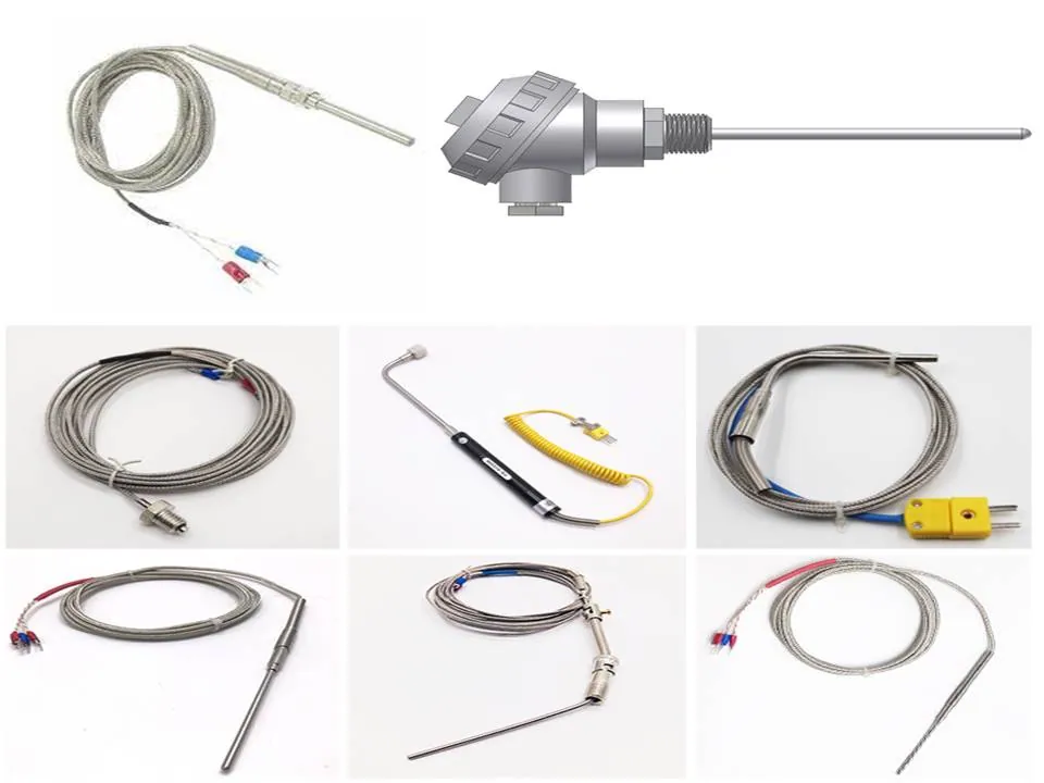
There are many different types of thermocouples, each with its own combination of metals and temperature ranges for which it is best suited. The most common types of thermocouples are:
K Type – made from nickel-chromium and nickel-aluminum, and can measure temperatures up to 1,372°C (2,502°F). They are widely used in the metal processing and petrochemical industries.
J Type – made from iron and constantan, and can measure temperatures up to 760°C (1,400°F). They are commonly used in low-temperature applications, such as food processing and refrigeration.
T Type – made from copper and constantan, and can measure temperatures up to 370°C (698°F). They are often used in cryogenics and low-temperature applications.
E Type – made from chromel and constantan, and can measure temperatures up to 870°C (1,598°F). They are commonly used in the chemical and power generation industries.
N Type – made from Nicrosil and Nisil, and can measure temperatures up to 1,200°C (2,192°F). They are often used in high-temperature applications, such as aerospace and nuclear power.
Type R and S – made from platinum and platinum-rhodium alloys, and can measure temperatures up to 1,768°C (3,214°F). They are commonly used in the ceramics and glass industries.
There are also less common types of thermocouples, such as Types B, C, and D, which are made from platinum and platinum-rhodium alloys and can measure even higher temperatures than Types R and S.
Thermocouple material
Thermocouples are made from two different metals joined together at one end to form a thermocouple junction. The two metals used to make a thermocouple are referred to as the thermocouple materials. There are many different types of thermocouple materials, but the most commonly used types are:
K Type : Type K thermocouples are made from chromel (90% nickel and 10% chromium) and alumel (95% nickel, 2% manganese, 2% aluminium, and 1% silicon). They have a temperature range of -200°C to 1260°C.
J Type : Type J thermocouples are made from iron and constantan (45% nickel and 55% copper). They have a temperature range of -210°C to 760°C.
T Type : Type T thermocouples are made from copper and constantan. They have a temperature range of -200°C to 350°C.
E Type : Type E thermocouples are made from chromel and constantan. They have a temperature range of -270°C to 1000°C.
N Type : Type N thermocouples are made from nicrosil (14% chromium, 1.5% silicon, 0.1% magnesium, and 0.03% aluminium) and nisil (4.5% silicon, 0.1% magnesium, and 0.03% aluminium). They have a temperature range of -270°C to 1300°C.
The choice of thermocouple material depends on the temperature range of the application, the accuracy required, and the environmental conditions.
What is RTD sensor?
An RTD sensor, or Resistance Temperature Detector, is a temperature sensor that measures temperature by sensing changes in the resistance of a metal wire as temperature changes. The most common metals used in RTD sensors are platinum, nickel, and copper.
An RTD sensor works by passing a current through a metal wire, and measuring the resulting voltage drop across the wire. As the temperature of the wire changes, the resistance of the wire also changes. This change in resistance causes a change in the voltage drop across the wire, which can be used to calculate the temperature.
RTD sensors are highly accurate and stable, and provide a linear output over a wide temperature range. They are commonly used in applications that require precise temperature measurement, such as laboratory and scientific settings, as well as in industrial process control and monitoring applications.
The most common type of RTD sensor is a platinum RTD, which is highly accurate and stable over a wide temperature range. Platinum RTDs are widely used in industrial, aerospace, and automotive applications.
What is the difference between an RTD and a Thermocouple?
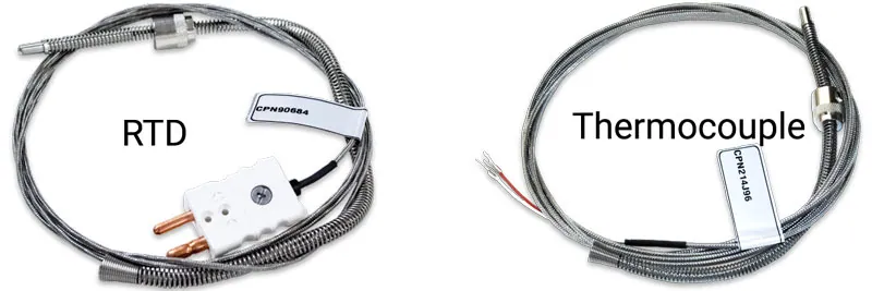
The main difference between a resistance temperature detector (RTD) and a thermocouple is the way they measure temperature.
An RTD measures temperature by sensing changes in the resistance of a metal wire as temperature changes. The metal wire is usually made of platinum, nickel, or copper. As temperature increases, the resistance of the wire increases proportionally. This change in resistance is then converted into a temperature reading using a calibration chart or equation.
A thermocouple, on the other hand, measures temperature by sensing the voltage generated when two different metals are joined together. The voltage produced is proportional to the temperature difference between the hot and cold junctions of the thermocouple. The hot junction is exposed to the temperature being measured, while the cold junction is usually kept at a known temperature, either by being placed in a thermally stable environment or by being connected to a reference junction at a known temperature. The voltage generated by the thermocouple is then converted into a temperature reading using a calibration chart or equation.
In terms of performance, RTDs generally provide higher accuracy and stability over a wider temperature range than thermocouples. RTDs are also less affected by electromagnetic interference and are more suitable for use in applications that require precise temperature measurements, such as in laboratory and scientific settings. Thermocouples, on the other hand, are more rugged and can operate in a wider temperature range than RTDs, making them ideal for use in industrial and high-temperature applications.
Which one is more accurate RTD sensor or Thermocouple sensor?
Both RTD (Resistance Temperature Detector) sensors and Thermocouple sensors are commonly used for temperature measurement, but each has its advantages and disadvantages.
RTD sensors are typically more accurate than thermocouples, with a typical accuracy of ±0.1°C to ±0.5°C. RTDs use the change in resistance of a metal wire as a function of temperature, and the resistance change is directly proportional to the temperature change. They have a linear response to temperature and a wide temperature range (-200°C to +850°C), which makes them suitable for a wide range of applications.
On the other hand, thermocouples have a typical accuracy of ±1°C to ±2°C. Thermocouples use the voltage generated by the junction of two dissimilar metals as a function of temperature. They have a non-linear response to temperature, and their accuracy depends on the material used and the temperature range.
In general, if you need high accuracy and precision in your temperature measurements, an RTD sensor may be the better choice. However, if you need to measure high temperatures or need a sensor that can withstand harsh environments, a thermocouple may be a better option. The choice of sensor depends on the specific application and its requirements.
What is PT100 sensor?
A PT100 sensor, also known as a platinum resistance thermometer (PRT), is a type of RTD (Resistance Temperature Detector) sensor. It is made of a platinum wire coil that changes its resistance as a function of temperature. The PT100 sensor is designed to have a resistance of 100 ohms at 0°C, and its resistance increases linearly with temperature. This change in resistance can be measured and used to accurately determine the temperature.
PT100 sensors are commonly used for temperature measurement in industrial and laboratory applications. They offer high accuracy, stability, and repeatability, with typical accuracies ranging from ±0.1°C to ±0.5°C. They have a wide temperature range, typically from -200°C to +850°C, and are resistant to corrosion and oxidation.
PT100 sensors can be used in a variety of applications, including HVAC (Heating, Ventilation, and Air Conditioning) systems, food processing, pharmaceuticals, and industrial process control. They are also used in research and scientific applications, where high accuracy and precision are required. PT100 sensors are commonly available in two, three, or four-wire configurations, depending on the level of accuracy required and the application.
Pt100 Wiring for Industrial Temperature Sensors
When wiring a PT100 industrial temperature sensor, it is important to follow the proper wiring guidelines to ensure accurate temperature readings. Here are some general guidelines:
Use the appropriate wire gauge and material: Use wire with a sufficient gauge to minimize resistance, typically 20 to 24 AWG. Copper wire is commonly used for shorter distances, while other materials like nickel, silver, or platinum may be used for longer distances or high-temperature applications.
Use shielded cable: Shielded cable can protect the signal from electromagnetic interference (EMI) and radio frequency interference (RFI).
Use the correct wiring configuration: PT100 sensors are commonly available in two, three, or four-wire configurations. The wiring configuration will depend on the level of accuracy required and the application. A four-wire configuration offers the highest level of accuracy, as it eliminates any errors due to lead resistance.
Connect the wires correctly: The PT100 sensor wires must be connected correctly to the appropriate terminals. The PT100 sensor has a positive lead (usually red) and a negative lead (usually white). For a two-wire configuration, the two leads are connected to the positive and negative terminals of the measuring instrument. For a three- or four-wire configuration, the wires are connected to the appropriate terminals to compensate for lead resistance.
Test the wiring: After wiring the PT100 sensor, it is important to test the wiring to ensure that the temperature readings are accurate. This can be done by comparing the temperature readings from the PT100 sensor to a calibrated thermometer or temperature measuring instrument.
By following these guidelines, you can ensure that the PT100 industrial temperature sensor is properly wired and provides accurate temperature readings for your application.
2 wire Pt100 RTD Sensor Wiring System

A 2-wire Pt100 RTD sensor wiring system is the simplest wiring configuration for a Pt100 sensor. It consists of two wires, one for the positive connection and one for the negative connection. Here are the steps for wiring a 2-wire Pt100 RTD sensor:
Identify the wires: The Pt100 sensor will have two wires, one with a positive lead (usually red) and one with a negative lead (usually white).
Connect the wires to the measuring instrument: Connect the positive wire to the positive terminal of the measuring instrument and the negative wire to the negative terminal of the measuring instrument.
Check for proper connection: Ensure that the connections are tight and secure, and there is no loose connection.
Test the sensor: After wiring the Pt100 sensor, test it to ensure it is working correctly. You can use a thermometer or a temperature measuring instrument to compare the temperature readings from the Pt100 sensor.
Note that the 2-wire configuration has some limitations. Due to the presence of lead resistance in the two wires, it can introduce errors in temperature readings. This configuration may not be suitable for applications where high accuracy is required. In such cases, a 3- or 4-wire configuration may be preferred to eliminate the errors due to lead resistance.
3 wire Pt100 RTD Sensor Wiring System
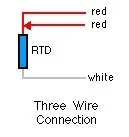
A 3-wire Pt100 RTD sensor wiring system is commonly used to reduce the impact of lead resistance on temperature measurement. This configuration uses three wires – two of the wires are connected to the Pt100 sensor and the third wire is connected to the measuring instrument. Here are the steps for wiring a 3-wire Pt100 RTD sensor:
Identify the wires: The Pt100 sensor will have three wires – two with the same color (usually red) and one with a different color (usually white).
Connect the wires to the measuring instrument: Connect one of the wires with the same color (usually red) to the positive terminal of the measuring instrument, and the wire with a different color (usually white) to the negative terminal of the measuring instrument. The other wire with the same color (usually red) is connected to a separate terminal on the measuring instrument.
Check for proper connection: Ensure that the connections are tight and secure, and there is no loose connection.
Test the sensor: After wiring the Pt100 sensor, test it to ensure it is working correctly. You can use a thermometer or a temperature measuring instrument to compare the temperature readings from the Pt100 sensor.
The 3-wire configuration can help to eliminate errors due to lead resistance, which can improve the accuracy of temperature measurement. However, it is important to note that the 3-wire configuration does not completely eliminate the lead resistance, and it is still present in one of the wires. For higher accuracy, a 4-wire configuration can be used.
4 wire Pt100 RTD Wiring System

A 4-wire Pt100 RTD wiring system is the most accurate wiring configuration for a Pt100 sensor. It uses four wires – two wires for the Pt100 sensor and two wires for the measuring instrument.
Here are the steps for wiring a 4-wire Pt100 RTD sensor:
Identify the wires: The Pt100 sensor will have four wires – two with one color (usually red) and two with another color (usually white).
Connect the wires to the measuring instrument: Connect one of the wires with one color (usually red) to the positive terminal of the measuring instrument, and one of the wires with the other color (usually white) to the negative terminal of the measuring instrument. The other two wires are connected to separate terminals on the measuring instrument.
Check for proper connection: Ensure that the connections are tight and secure, and there is no loose connection.
Test the sensor: After wiring the Pt100 sensor, test it to ensure it is working correctly. You can use a thermometer or a temperature measuring instrument to compare the temperature readings from the Pt100 sensor.
The 4-wire configuration eliminates the errors due to lead resistance in the two wires that connect the Pt100 sensor to the measuring instrument. This results in the most accurate temperature measurements. However, it requires more wiring and more connections, which can be more complex and expensive than the 2- or 3-wire configurations.
How to choose a thermocouple?
Choosing a thermocouple involves considering various factors to ensure it meets the specific requirements of your application. Thermocouples are temperature sensors that generate a voltage proportional to the temperature difference between two junctions.
Temperature Range:
Determine the temperature range of your application. Different thermocouple types are suitable for different temperature ranges. Common types include Type K (wide range), Type J (medium range), and Type T (low range).
Chemical Compatibility:
Consider the environment in which the thermocouple will be used. Some materials may corrode or react with certain chemicals. Choose a thermocouple with materials that are compatible with your application.
Accuracy and Sensitivity:
Different thermocouple types have different levels of accuracy and sensitivity. Type S and Type R thermocouples, for example, offer high accuracy but are more expensive than Type K or Type J thermocouples. Consider the level of precision required for your application.
Response Time:
The response time of a thermocouple is the time it takes to register a change in temperature. If your application requires a fast response time, choose a thermocouple with a quick response.
Cost:
Consider your budget constraints. Thermocouples vary in cost, with some types being more expensive than others. Balance your requirements with the available budget.
Application Environment:
Consider the physical conditions of the environment where the thermocouple will be used. For example, if the application involves vibrations or mechanical stress, choose a thermocouple that can withstand such conditions.
Installation Requirements:
Consider the ease of installation and the physical constraints of your setup. Some thermocouples are more flexible and easier to install than others.
Output Voltage:
Different thermocouples produce different voltage outputs for the same temperature. Ensure that the output voltage range is compatible with your measurement equipment.
Wire Insulation:
Choose the appropriate insulation for the thermocouple wires. Common insulations include fiberglass, Teflon, and ceramic. The insulation material should be suitable for the temperature range and environmental conditions.
Standards and Regulations:
Ensure that the thermocouple complies with any relevant industry standards or regulations applicable to your application.
Long-Term Stability:
Consider the long-term stability of the thermocouple material. Some thermocouples may drift over time, affecting accuracy.
Application of a Thermocouple
A thermocouple is a temperature measurement device that consists of two different metals joined at one end. When the junction of the two metals is heated or cooled, a voltage is generated that can be correlated with the temperature. Thermocouples are widely used for various temperature measurement applications due to their simplicity, durability, and cost-effectiveness.
Some common applications of thermocouples:
Industrial Temperature Monitoring:
Manufacturing Processes: Thermocouples are extensively used in industries to monitor temperatures during various manufacturing processes such as metal production, glass manufacturing, and chemical processing.
HVAC Systems:
Temperature Control: Thermocouples are employed in heating, ventilation, and air conditioning (HVAC) systems to measure and control temperatures. They help maintain comfortable and consistent temperatures in residential and commercial buildings.
Food Industry:
Cooking and Baking: Thermocouples are used in ovens and other cooking equipment to monitor and control the temperature, ensuring that food is cooked or baked at the desired temperature.
Medical Applications:
Body Temperature Measurement: Some medical devices, such as thermometers, use thermocouples to measure body temperature. Infrared thermocouples are also used for non-contact temperature measurement in medical applications.
Aerospace Industry:
Aircraft Engines: Thermocouples are utilized in aircraft engines to measure exhaust gas temperature, helping monitor engine performance and prevent overheating.
Power Plants:
Steam Generators and Boilers: Thermocouples play a crucial role in power plants, especially in monitoring and controlling the temperature of steam generators and boilers to ensure efficient and safe operation.
Research and Laboratory Applications:
Scientific Experiments: Thermocouples are commonly used in research laboratories for various scientific experiments where precise temperature measurement is essential.
Automotive Industry:
Exhaust System Monitoring: Thermocouples are integrated into the exhaust systems of vehicles to measure exhaust gas temperature. This information is crucial for optimizing fuel efficiency and reducing emissions.
Oil and Gas Industry:
Well Monitoring: In the oil and gas industry, thermocouples are used to monitor temperatures in wells and pipelines. They help ensure that equipment operates within safe temperature ranges.
Electronics Cooling:
Electronic Devices: Thermocouples are employed to monitor the temperature of electronic components and devices, helping prevent overheating and damage.
Environmental Monitoring:
Climate Research: Thermocouples are used in environmental monitoring stations to measure air and water temperatures, contributing to climate research and weather forecasting.
FAQ
What is RTD and thermocouple?
Resistance Temperature Detectors (RTD) and Thermocouples are the most common sensor types used to measure temperatures.
What is called thermocouple?
A thermocouple is a device used for measuring temperature. It consists of two dissimilar metal wires, called thermoelements, that are joined together at one end to form a junction.
Where is thermocouple used?
Thermocouples are used in applications that range from home appliances to industrial processes, to electric power generation, to furnace monitoring and control, to food and beverage processing, to automotive sensors, to aircraft engines, to rockets, satellites and spacecraft.
You may also like